Nissan Pathfinder (2005 year). Manual - part 388
PREPARATION
RFD-5
C
E
F
G
H
I
J
K
L
M
A
B
RFD
2005 Pathfinder
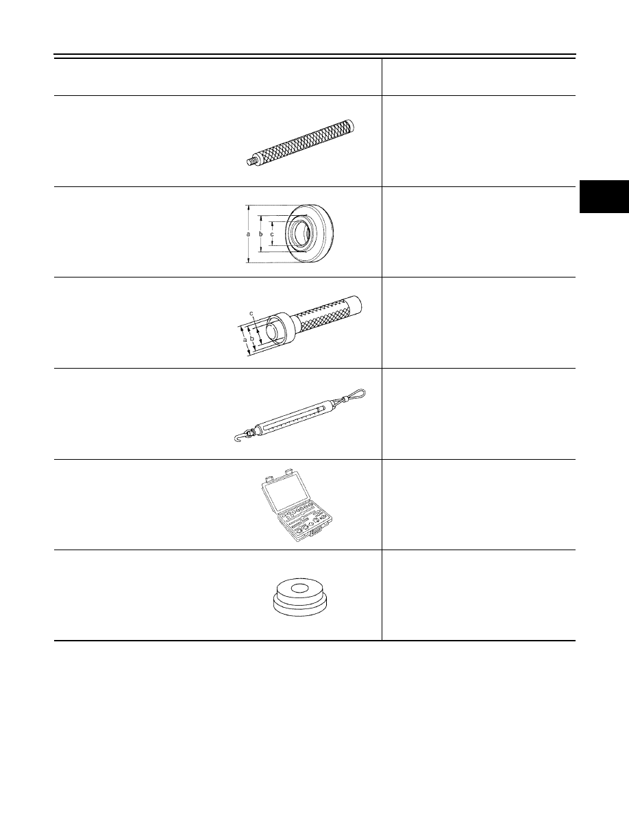
ST30611000
(J-25742-1)
Drift bar
Installing pinion front bearing outer race (Use
with ST30613000)
ST30901000
(J-26010-01)
Drift
Installing pinion rear bearing inner race
a: 79 mm (3.11 in) dia.
b: 45 mm (1.77 in) dia.
c: 35.2 mm (1.386 in) dia.
KV38100300
(J-25523)
Drift
Installing side bearing inner race
a: 54 mm (2.13 in) dia.
b: 46 mm (1.81 in) dia.
c: 32 mm (1.26 in) dia.
(J-8129)
Spring gauge
Measuring turning torque
(J-34309)
Differential shim selector tool
Adjusting bearing preload and pinion gear
height
(J-25269-4)
Side bearing disc (2 Req'd)
Selecting pinion height adjusting washer
Tool number
(Kent-Moore No.)
Tool name
Description
S-NT090
ZZA0978D
ZZA1046D
NT127
NT134
NT136