Nissan Pathfinder (2005 year). Manual - part 386


  Index      Manuals     Nissan Pathfinder (2005 year) - Service and Repair Manual


Search            copyright infringement  


Content      ..     384      385      386      387     ..


Nissan Pathfinder (2005 year). Manual - part 386


SUNROOF

RF-19

C

D

E

F

G

H

J

K

L

M

A

B

RF

2005 Pathfinder

3.

CHECK GROUND CIRCUIT

1.

Turn ignition switch OFF.

2.

Check continuity between BCM connector M20 terminal 67 and ground.

OK or NG

OK

>> Power supply and ground circuits are OK.

NG

>> Repair or replace harness.

Sunroof Switch System Check

EIS004ZP

1.

SUNROOF SWITCH INPUT SIGNAL CHECK

1.

Turn ignition switch ON.

2.

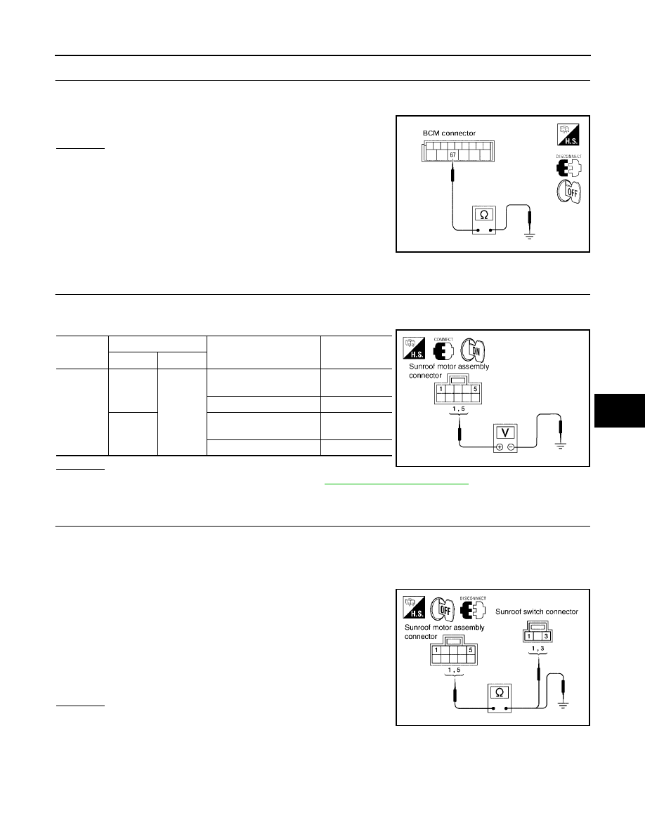
Check voltage between sunroof motor assembly connector and ground.

OK or NG

OK

>> Replace sunroof motor assembly. Refer to

RF-27, "SUNROOF MOTOR"

.

NG

>> GO TO 2.

2.

SUNROOF SWITCH CIRCUIT CHECK

1.

Turn ignition switch OFF.

2.

Disconnect sunroof motor assembly and sunroof switch connectors.

3.

Check continuity between sunroof motor assembly connector B83 terminals 1, 5 and sunroof switch con-
nector R4 terminals 1, 3.

4.

Check continuity between sunroof motor assembly connector
B83 terminals 1, 5 and ground.

OK or NG

OK

>> GO TO 3.

NG

>> Repair or replace harness between sunroof motor

assembly and sunroof switch.

67 - Ground

: Continuity should exist.

LIIA0915E

Connector

Terminal

Condition

Voltage

(Approx.)

(+)

(–)

B83

1

Ground

Sunroof switch is operated
to UP/CLOSE

0

Other than above

Battery voltage

5

Sunroof switch is operated
to DOWN/OPEN

0

Other than above

Battery voltage

WIIA0436E

1 - 3

: Continuity should exist.

5 - 1

: Continuity should exist.

1 - Ground

: Continuity should not exist.

5 - Ground

: Continuity should not exist.

WIIA0437E

RF-20

SUNROOF

2005 Pathfinder

3.

SUNROOF SWITCH GROUND CIRCUIT CHECK

Check continuity between sunroof switch connector R4 terminal 2 and ground.

OK or NG

OK

>> GO TO 4.

NG

>> Repair or replace harness.

4.

SUNROOF SWITCH CHECK

Check continuity between sunroof switch terminals 1, 3 and 2.

OK or NG

OK

>> Replace sunroof motor assembly. Refer to

RF-27,

"SUNROOF MOTOR"

.

NG

>> Replace sunroof switch.

Sunroof Motor Assembly Power Supply and Ground Circuit Check

EIS004ZQ

1.

CHECK POWER SUPPLY CIRCUIT

1.

Turn ignition switch ON.

2.

Check voltage between sunroof motor assembly connector B83 terminals 7, 9 and ground.

OK or NG

OK

>> GO TO 2.

NG

>> GO TO 3.

2 - Ground

: Continuity should exist.

PIIA3627E

Terminals

Condition

Continuity

1

2

Sunroof switch is operated to
DOWN/OPEN

Yes

Other than above

No

3

Sunroof switch is operated to
UP/CLOSE

Yes

Other than above

No

PIIA6157E

7 - Ground

: Battery voltage

9 - Ground

: Battery voltage

WIIA0438E

SUNROOF

RF-21

C

D

E

F

G

H

J

K

L

M

A

B

RF

2005 Pathfinder

2.

CHECK GROUND CIRCUIT

1.

Turn ignition switch OFF.

2.

Disconnect sunroof motor assembly connector.

3.

Check continuity between sunroof motor assembly connector B83 terminal 10 and ground.

OK or NG

OK

>> Sunroof motor assembly power supply and ground cir-

cuits are OK. Further inspection is necessary. Refer to

RF-18, "Trouble Diagnosis Chart by Symptom"

.

NG

>> Repair or replace harness.

3.

CHECK BCM OUTPUT SIGNAL

1.

Turn ignition switch ON.

2.

Check voltage between BCM connector M20 terminals 68, 69
and ground.

OK or NG

OK

>> GO TO 4.

NG

>> Replace BCM. Refer to

BCS-19, "Removal and Installa-

tion of BCM"

.

4.

CHECK SUNROOF MOTOR CIRCUIT

1.

Turn ignition switch OFF.

2.

Disconnect BCM and sunroof motor assembly connectors.

3.

Check continuity between BCM connector M20 terminals 68, 69 and sunroof motor assembly connector
B83 terminals 7, 9.

4.

Check continuity between BCM connector M20 terminals 68, 69
and ground.

OK or NG

OK

>> Sunroof motor assembly power supply circuits are OK.

Further inspection is necessary. Refer to

RF-18, "Trou-

ble Diagnosis Chart by Symptom"

.

NG

>> Repair or replace harness.

10 - Ground

: Continuity should exist.

WIIA0439E

68 - Ground

: Battery voltage

69 - Ground

: Battery voltage

WIIA0425E

68 - 9

: Continuity should exist.

69 - 7

: Continuity should exist.

68 - Ground

: Continuity should not exist.

69 - Ground

: Continuity should not exist.

LIIA1683E

RF-22

SUNROOF

2005 Pathfinder

Door Switch Check

EIS004ZR

1.

CHECK DOOR SWITCH INPUT SIGNAL

With CONSULT-II

Check ("DOOR SW-DR" and "DOOR SW-AS") in "DATA MONITOR" mode with CONSULT-II.

Without CONSULT-II

Check voltage between BCM connector M18, M19 terminals 12, 47 and ground.

OK or NG

OK

>> Door switches are OK.

NG

>> GO TO 2.

Monitor item

Condition

DOOR SW-DR

OPEN

: ON

CLOSE

: OFF

DOOR SW-AS

OPEN

: ON

CLOSE

: OFF

PIIA2464E

Item

Terminal

Condition

Voltage

(Approx.)

(+)

(–)

RH door switch

12

Ground

OPEN

0

CLOSE

Battery voltage

LH door switch

47

OPEN

0

CLOSE

Battery voltage

WIIA0234E

SUNROOF

RF-23

C

D

E

F

G

H

J

K

L

M

A

B

RF

2005 Pathfinder

2.

CHECK DOOR SWITCH CIRCUIT

1.

Turn ignition switch OFF.

2.

Disconnect door switch and BCM connectors.

3.

Check continuity between BCM connector M18, M19 terminals
12, 47 and door switch connectors B8, B108 terminal 2.

4.

Check continuity between BCM connector M18, M19 terminals
12, 47 and ground.

OK or NG

OK

>> GO TO 3.

NG

>> Repair or replace harness.

3.

CHECK DOOR SWITCH

Check continuity between door switches terminal 2 and ground part
of door switch.

OK or NG

OK

>> GO TO 4.

NG

>> Replace malfunctioning door switch.

4.

CHECK BCM OUTPUT SIGNAL

1.

Connect BCM connectors.

2.

Check voltage between BCM connector M18, M19 terminals 12,
47 and ground.

OK or NG

OK

>> Further inspection is necessary. Refer to

RF-18, "Trou-

ble Diagnosis Chart by Symptom"

.

NG

>> Replace BCM. Refer to

BCS-19, "Removal and Installa-

tion of BCM"

.

Front door LH

47 - 2

: Continuity should exist.

Front door RH

12 - 2

: Continuity should exist.

12 - Ground

: Continuity should not exist.

47 - Ground

: Continuity should not exist.

WIIA0426E

Terminal

Door switch

Continuity

2

Ground part of

door switch

Pushed

No

Released

Yes

LIIA0948E

12 - Ground

: Battery voltage

47 - Ground

: Battery voltage

WIIA0234E

RF-24

SUNROOF

2005 Pathfinder

Fitting Adjustment

EIS0043T

GAP ADJUSTMENT

NOTE:
If any gap or height difference between glass lid and roof panel is found, check glass lid fit and adjust as fol-
lows:
1.

Open sunshade assembly.

2.

Loosen glass lid securing screws (2 each on left and right sides), then tilt glass lid down.

3.

Manually adjust glass lid from outside of vehicle so it resembles "A-A" as shown in the figure.

4.

After adjusting glass lid, tilt glass lid up and tighten screws.

5.

Tilt glass lid up and down several times to check that it moves smoothly.

HEIGHT DIFFERENCE ADJUSTMENT

1.

Tilt glass lid up and down.

2.

Check height difference between roof panel and glass lid, and compare to "A-A".

LIIA1671E

SUNROOF

RF-25

C

D

E

F

G

H

J

K

L

M

A

B

RF

2005 Pathfinder

Removal and Installation

EIS0043U

WIIA0423E

RF-26

SUNROOF

2005 Pathfinder

After any adjustment, check sunroof operation and glass lid alignment.

Handle glass lid with care so not to cause damage.

For easier installation, mark each point before removal.

CAUTION:

Always work with a helper.

Before removal, fully close the glass lid assembly. Then, after removal, do not move the motor
assembly.

After installing the sunroof and glass lid, check gap adjustment to ensure there is no malfunction.

SUNROOF UNIT
Removal

CAUTION:

Always work with a helper.

When taking sunroof unit out, use shop cloths to protect the seats and trim from damage.

After installing the sunroof unit and glass lid, be sure to check gap adjustment to ensure there is
no malfunction.

1.

Remove headlining. Refer to

EI-30, "Removal and Installation"

.

2.

Remove the sunroof glass lid. Refer to

RF-26, "GLASS LID"

.

3.

Remove the overhead console bracket.

4.

Disconnect the drain hoses.

5.

Remove front sunroof nuts.

6.

Remove the rear sunroof bracket bolts.

7.

Remove the side bolts and the sunroof unit.

Installation

1.

Position the sunroof frame assembly and install the side bolts.

2.

Install the rear sunroof bracket bolts.

3.

Install front sunroof nuts.

4.

Connect the drain hoses.

5.

Install the overhead console bracket.

6.

Install the sunroof glass lid. Refer to

RF-26, "GLASS LID"

.

7.

Install headlining. Refer to

EI-30, "Removal and Installation"

.

GLASS LID
Removal

1.

Open sunshade.

2.

Ensure glass lid is closed.

3.

Remove the screws securing glass lid to the sunroof frame assembly.

4.

Remove the glass lid assembly.

Installation

1.

Position glass lid to sunroof assembly.

1.

Glass lid assembly

2.

Wind deflector

3.

Rear drain hoses

4.

Shade stoppers

5.

Sunroof bracket

6.

Sunroof frame assembly

7.

Front drain hoses

8.

Sunroof motor assembly

9.

Sunshade assembly


Content      ..     384      385      386      387     ..