Nissan Pathfinder (2005 year). Manual - part 310
CAN SYSTEM (TYPE 5)
LAN-179
[CAN]
C
D
E
F
G
H
I
J
L
M
A
B
LAN
2005 Pathfinder
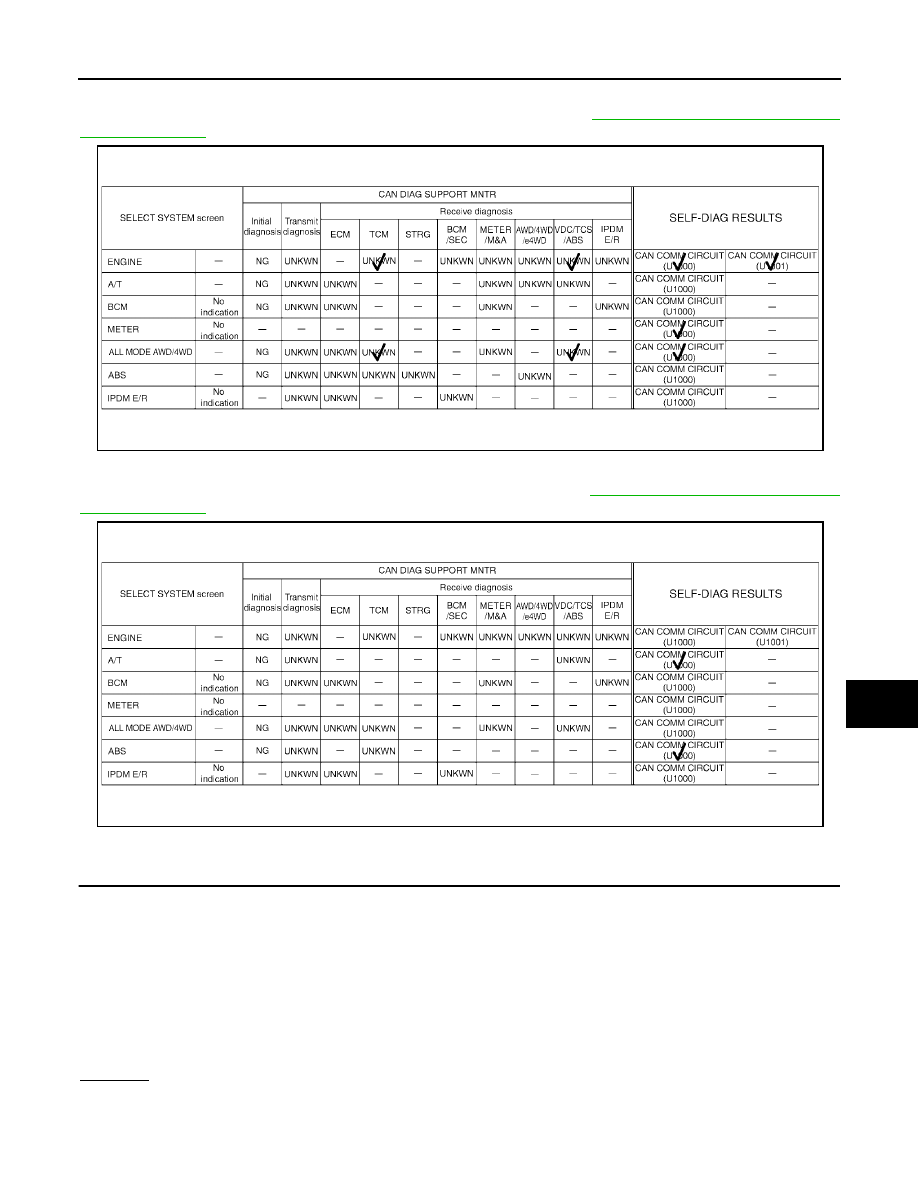
Case 13
Check IPDM E/R ignition relay circuit continuously sticks “OFF”. Refer to
LAN-190, "IPDM E/R Ignition Relay
.
Case 14
Check IPDM E/R ignition relay circuit continuously sticks “ON”. Refer to
LAN-190, "IPDM E/R Ignition Relay
.
Inspection Between TCM and Data Link Connector Circuit
UKS003E2
1.
CHECK CONNECTOR
1.
Turn ignition switch OFF.
2.
Disconnect the battery cable from the negative terminal.
3.
Check following terminals and connectors for damage, bend and loose connection (connector side and
harness side).
–
Harness connector F14
–
Harness connector E5
–
Harness connector E152
–
Harness connector M31
OK or NG
OK
>> GO TO 2.
NG
>> Repair terminal or connector.
PKIB5139E
PKIB5140E