Nissan Pathfinder (2005 year). Manual - part 306


  Index      Manuals     Nissan Pathfinder (2005 year) - Service and Repair Manual


Search            copyright infringement  


Content      ..     304      305      306      307     ..


Nissan Pathfinder (2005 year). Manual - part 306


CAN SYSTEM (TYPE 4)

LAN-147

[CAN]

C

D

E

F

G

H

I

J

L

M

A

B

LAN

2005 Pathfinder

Inspection Between Display Control Unit and Data Link Connector Circuit

UKS003EL

1.

CHECK HARNESS FOR OPEN CIRCUIT

1.

Turn ignition switch OFF.

2.

Disconnect the battery cable from the negative terminal.

3.

Disconnect ECM connector and display control unit connector.

4.

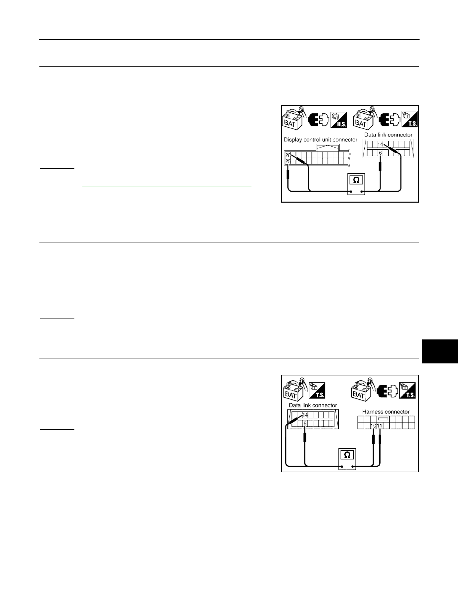
Check continuity between display control unit harness connector
M95 terminals 25 (L), 26 (P) and data link connector M22 termi-
nals 6 (L), 14 (P).

OK or NG

OK

>> Connect all the connectors and diagnose again. Refer to

LAN-6, "TROUBLE DIAGNOSES WORK FLOW"

.

NG

>> Repair harness.

Inspection Between Data Link Connector and ABS Actuator and Electric Unit
(Control Unit) Circuit

UKS003EM

1.

CHECK CONNECTOR

1.

Turn ignition switch OFF.

2.

Disconnect the battery cable from the negative terminal.

3.

Check following terminals and connectors for damage, bend and loose connection (connector side and
harness side).

Harness connector M91

Harness connector E26

OK or NG

OK

>> GO TO 2.

NG

>> Repair terminal or connector.

2.

CHECK HARNESS FOR OPEN CIRCUIT

1.

Disconnect harness connector M91.

2.

Check continuity between data link connector M22 terminals 6
(L), 14 (P) and harness connector M91 terminals 11 (L), 10 (P).

OK or NG

OK

>> GO TO 3.

NG

>> Repair harness.

25 (L) – 6 (L)

: Continuity should exist.

26 (P) – 14 (P)

: Continuity should exist.

SKIB2811E

6 (L) – 11 (L)

: Continuity should exist.

14 (P) – 10 (P)

: Continuity should exist.

SKIB2812E

LAN-148

[CAN]

CAN SYSTEM (TYPE 4)

2005 Pathfinder

3.

CHECK HARNESS FOR OPEN CIRCUIT

1.

Disconnect ABS actuator and electric unit (control unit) connector.

2.

Check continuity between harness connector E26 terminals 11
(L), 10 (P) and ABS actuator and electric unit (control unit) har-
ness connector E125 terminals 11 (L), 15 (P).

OK or NG

OK

>> Connect all the connectors and diagnose again. Refer to

LAN-6, "TROUBLE DIAGNOSES WORK FLOW"

.

NG

>> Repair harness.

ECM Circuit Inspection

UKS003EN

1.

CHECK CONNECTOR

1.

Turn ignition switch OFF.

2.

Disconnect the battery cable from the negative terminal.

3.

Check following terminals and connectors for damage, bend and loose connection (control module side
and harness side).

ECM connector

Harness connector E2

Harness connector F32

OK or NG

OK

>> GO TO 2.

NG

>> Repair terminal or connector.

2.

CHECK HARNESS FOR OPEN CIRCUIT

1.

Disconnect ECM connector.

2.

Check resistance between ECM harness connector E16 termi-
nals 94 (L) and 86 (P).

OK or NG

OK

>> Replace ECM.

NG

>> Repair harness between ECM and A/T assembly.

TCM Circuit Inspection

UKS003EO

1.

CHECK CONNECTOR

1.

Turn ignition switch OFF.

2.

Disconnect the battery cable from the negative terminal.

3.

Check terminals and connector of A/T assembly for damage, bend and loose connection (control module
side and harness side).

OK or NG

OK

>> GO TO 2.

NG

>> Repair terminal or connector.

11 (L) – 11 (L)

: Continuity should exist.

10 (P) – 15 (P)

: Continuity should exist.

SKIB2813E

94 (L) – 86 (P)

: Approx. 108 – 132

PKIA9592E

CAN SYSTEM (TYPE 4)

LAN-149

[CAN]

C

D

E

F

G

H

I

J

L

M

A

B

LAN

2005 Pathfinder

2.

CHECK HARNESS FOR OPEN CIRCUIT

1.

Disconnect A/T assembly connector.

2.

Check resistance between A/T assembly harness connector F9
terminals 3 (L) and 8 (P).

OK or NG

OK

>> Replace control valve with TCM.

NG

>> Repair harness between A/T assembly and harness

connector F14.

Display Control Unit Circuit Inspection

UKS003EP

1.

CHECK CONNECTOR

1.

Turn ignition switch OFF.

2.

Disconnect the battery cable from the negative terminal.

3.

Check terminals and connector of display control unit for damage, bend and loose connection (control unit
side and harness side).

OK or NG

OK

>> GO TO 2.

NG

>> Repair terminal or connector.

2.

CHECK HARNESS FOR OPEN CIRCUIT

1.

Disconnect display control unit connector.

2.

Check resistance between display control unit harness connec-
tor M95 terminals 25 (L) and 26 (P).

OK or NG

OK

>> Replace display control unit.

NG

>> Repair harness between display control unit and har-

ness connector M31.

Front Air Control Circuit Inspection

UKS003EQ

1.

CHECK CONNECTOR

1.

Turn ignition switch OFF.

2.

Disconnect the battery cable from the negative terminal.

3.

Check terminals and connector of front air control for damage, bend and loose connection (unit side and
harness side).

OK or NG

OK

>> GO TO 2.

NG

>> Repair terminal or connector.

3 (L) – 8 (P)

: Approx. 54 – 66

SKIA6866E

25 (L) – 26 (P)

: Approx. 54 – 66

SKIA6884E

LAN-150

[CAN]

CAN SYSTEM (TYPE 4)

2005 Pathfinder

2.

CHECK HARNESS FOR OPEN CIRCUIT

1.

Disconnect front air control connector.

2.

Check resistance between front air control harness connector
M50 terminals 41 (L) and 42 (P).

OK or NG

OK

>> Replace front air control.

NG

>> Repair harness between front air control and data link

connector.

Steering Angle Sensor Circuit Inspection

UKS003ER

1.

CHECK CONNECTOR

1.

Turn ignition switch OFF.

2.

Disconnect the battery cable from the negative terminal.

3.

Check terminals and connector of steering angle sensor for damage, bend and loose connection (sensor
side and harness side).

OK or NG

OK

>> GO TO 2.

NG

>> Repair terminal or connector.

2.

CHECK HARNESS FOR OPEN CIRCUIT

1.

Disconnect steering angle sensor connector.

2.

Check resistance between steering angle sensor harness con-
nector M47 terminals 3 (L) and 4 (P).

OK or NG

OK

>> Replace steering angle sensor.

NG

>> Repair harness between steering angle sensor and data

link connector.

Data Link Connector Circuit Inspection

UKS003ES

1.

CHECK CONNECTOR

1.

Turn ignition switch OFF.

2.

Disconnect the battery cable from the negative terminal.

3.

Check the terminals and connector of data link connector for damage, bend and loose connection (con-
nector side and harness side).

OK or NG

OK

>> GO TO 2.

NG

>> Repair terminal or connector.

41 (L) – 42 (P)

: Approx. 54 – 66

SKIB2814E

3 (L) – 4 (P)

: Approx. 54 – 66

PKIA6838E

CAN SYSTEM (TYPE 4)

LAN-151

[CAN]

C

D

E

F

G

H

I

J

L

M

A

B

LAN

2005 Pathfinder

2.

CHECK HARNESS FOR OPEN CIRCUIT

Check resistance between data link connector M22 terminals 6 (L)
and 14 (P).

OK or NG

OK

>> Diagnose again. Refer to

LAN-6, "TROUBLE DIAG-

NOSES WORK FLOW"

.

NG

>> Repair harness between data link connector and BCM.

BCM Circuit Inspection

UKS003ET

1.

CHECK CONNECTOR

1.

Turn ignition switch OFF.

2.

Disconnect the battery cable from the negative terminal.

3.

Check terminals and connector of BCM for damage, bend and loose connection (control module side and
harness side).

OK or NG

OK

>> GO TO 2.

NG

>> Repair terminal or connector.

2.

CHECK HARNESS FOR OPEN CIRCUIT

1.

Disconnect BCM connector.

2.

Check resistance between BCM harness connector M18 termi-
nals 39 (L) and 40 (P).

OK or NG

OK

>> Replace BCM. Refer to

BCS-19, "Removal and Installa-

tion of BCM"

.

NG

>> Repair harness between BCM and data link connector.

Combination Meter Circuit Inspection

UKS003EU

1.

CHECK CONNECTOR

1.

Turn ignition switch OFF.

2.

Disconnect the battery cable from the negative terminal.

3.

Check terminals and connector of combination meter for damage, bend and loose connection (meter side
and harness side).

OK or NG

OK

>> GO TO 2.

NG

>> Repair terminal or connector.

6 (L) – 14 (P)

: Approx. 54 – 66

SKIA6868E

39 (L) – 40 (P)

: Approx. 54 – 66

SKIA6869E

LAN-152

[CAN]

CAN SYSTEM (TYPE 4)

2005 Pathfinder

2.

CHECK HARNESS FOR OPEN CIRCUIT

1.

Disconnect combination meter connector.

2.

Check resistance between combination meter harness connec-
tor M24 terminals 12 (L) and 11 (P).

OK or NG

OK

>> Replace combination meter.

NG

>> Repair harness between combination meter and data

link connector.

Driver Seat Control Unit Circuit Inspection

UKS003EV

1.

CHECK CONNECTOR

1.

Turn ignition switch OFF.

2.

Disconnect the battery cable from the negative terminal.

3.

Check following terminals and connectors for damage, bend and loose connection (control unit side and
harness side).

Driver seat control unit connector

Harness connector P1

Harness connector B37

Harness connector B69

Harness connector M40

OK or NG

OK

>> GO TO 2.

NG

>> Repair terminal or connector.

2.

CHECK HARNESS FOR OPEN CIRCUIT

1.

Disconnect driver seat control unit connector.

2.

Check resistance between driver seat control unit harness con-
nector P2 terminals 3 (L) and 19 (P).

OK or NG

OK

>> Replace driver seat control unit.

NG

>> Repair harness between driver seat control unit and

data link connector.

ABS Actuator and Electric Unit (Control Unit) Circuit Inspection

UKS003EW

1.

CHECK CONNECTOR

1.

Turn ignition switch OFF.

2.

Disconnect the battery cable from the negative terminal.

3.

Check terminals and connector of ABS actuator and electric unit (control unit) for damage, bend and loose
connection (control unit side and harness side).

OK or NG

OK

>> GO TO 2.

NG

>> Repair terminal or connector.

12 (L) – 11 (P)

: Approx. 54 – 66

PKIA6837E

3 (L) – 19 (P)

: Approx. 54 – 66

PKIA6842E

CAN SYSTEM (TYPE 4)

LAN-153

[CAN]

C

D

E

F

G

H

I

J

L

M

A

B

LAN

2005 Pathfinder

2.

CHECK HARNESS FOR OPEN CIRCUIT

1.

Disconnect ABS actuator and electric unit (control unit) connector.

2.

Check resistance between ABS actuator and electric unit (con-
trol unit) harness connector E125 terminals 11 (L) and 15 (P).

OK or NG

OK

>> Replace ABS actuator and electric unit (control unit).

NG

>> Repair harness between ABS actuator and electric unit

(control unit) and IPDM E/R.

IPDM E/R Circuit Inspection

UKS003EX

1.

CHECK CONNECTOR

1.

Turn ignition switch OFF.

2.

Disconnect the battery cable from the negative terminal.

3.

Check terminals and connector of IPDM E/R for damage, bend and loose connection (control module side
and harness side).

OK or NG

OK

>> GO TO 2.

NG

>> Repair terminal or connector.

2.

CHECK HARNESS FOR OPEN CIRCUIT

1.

Disconnect IPDM E/R connector.

2.

Check resistance between IPDM E/R harness connector E122
terminals 39 (L) and 40 (P).

OK or NG

OK

>> Replace IPDM E/R.

NG

>> Repair harness between IPDM E/R and ABS actuator

and electric unit (control unit).

11 (L) – 15 (P)

: Approx. 54 – 66

SKIA6872E

39 (L) – 40 (P)

: Approx. 108 – 132

PKIA8141E

LAN-154

[CAN]

CAN SYSTEM (TYPE 4)

2005 Pathfinder

CAN Communication Circuit Inspection

UKS003EY

1.

CHECK CONNECTOR

1.

Turn ignition switch OFF.

2.

Disconnect the battery cable from the negative terminal.

3.

Check following terminals and connectors for damage, bend and loose connection (control module side,
control unit side, sensor side, meter side, and harness side).

ECM

TCM

Display control unit

Front air control

Steering angle sensor

BCM

Combination meter

Driver seat control unit

ABS actuator and electric unit (control unit)

IPDM E/R

Between ECM and IPDM E/R

Between ECM and driver seat control unit

OK or NG

OK

>> GO TO 2.

NG

>> Repair terminal or connector.

2.

CHECK HARNESS FOR SHORT CIRCUIT

1.

Disconnect following connectors.

ECM connector

Harness connector E2

2.

Check continuity between ECM harness connector E16 termi-
nals 94 (L) and 86 (P).

OK or NG

OK

>> GO TO 3.

NG

>> Repair harness between ECM and harness connector

E2.

3.

CHECK HARNESS FOR SHORT CIRCUIT

Check continuity between ECM harness connector E16 terminals 94
(L), 86 (P) and ground.

OK or NG

OK

>> GO TO 4.

NG

>> Repair harness between ECM and harness connector

E2.

94 (L) –86 (P)

: Continuity should not exist.

SKIA6865E

94 (L) – Ground

: Continuity should not exist.

86 (P) – Ground

: Continuity should not exist.

SKIB0571E


Content      ..     304      305      306      307     ..