Nissan Pathfinder (2005 year). Manual - part 302
CAN SYSTEM (TYPE 3)
LAN-115
[CAN]
C
D
E
F
G
H
I
J
L
M
A
B
LAN
2005 Pathfinder
2.
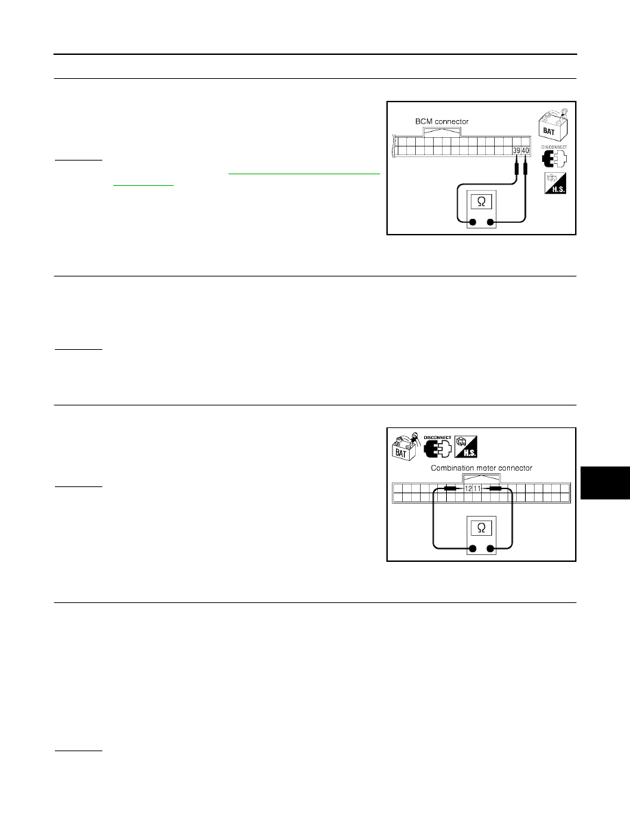
CHECK HARNESS FOR OPEN CIRCUIT
1.
Disconnect BCM connector.
2.
Check resistance between BCM harness connector M18 termi-
nals 39 (L) and 40 (P).
OK or NG
OK
>> Replace BCM. Refer to
BCS-19, "Removal and Installa-
.
NG
>> Repair harness between BCM and data link connector.
Combination Meter Circuit Inspection
UKS003FD
1.
CHECK CONNECTOR
1.
Turn ignition switch OFF.
2.
Disconnect the battery cable from the negative terminal.
3.
Check terminals and connector of combination meter for damage, bend and loose connection (meter side
and harness side).
OK or NG
OK
>> GO TO 2.
NG
>> Repair terminal or connector.
2.
CHECK HARNESS FOR OPEN CIRCUIT
1.
Disconnect combination meter connector.
2.
Check resistance between combination meter harness connec-
tor M24 terminals 12 (L) and 11 (P).
OK or NG
OK
>> Replace combination meter.
NG
>> Repair harness between combination meter and data
link connector.
Driver Seat Control Unit Circuit Inspection
UKS003FE
1.
CHECK CONNECTOR
1.
Turn ignition switch OFF.
2.
Disconnect the battery cable from the negative terminal.
3.
Check following terminals and connectors for damage, bend and loose connection (control unit side and
harness side).
–
Driver seat control unit connector
–
Harness connector P1
–
Harness connector B37
–
Harness connector B69
–
Harness connector M40
OK or NG
OK
>> GO TO 2.
NG
>> Repair terminal or connector.
39 (L) – 40 (P)
: Approx. 54 – 66
Ω
SKIA6869E
12 (L) – 11 (P)
: Approx. 54 – 66
Ω
PKIA6837E