Nissan Pathfinder (2005 year). Manual - part 301
CAN SYSTEM (TYPE 3)
LAN-107
[CAN]
C
D
E
F
G
H
I
J
L
M
A
B
LAN
2005 Pathfinder
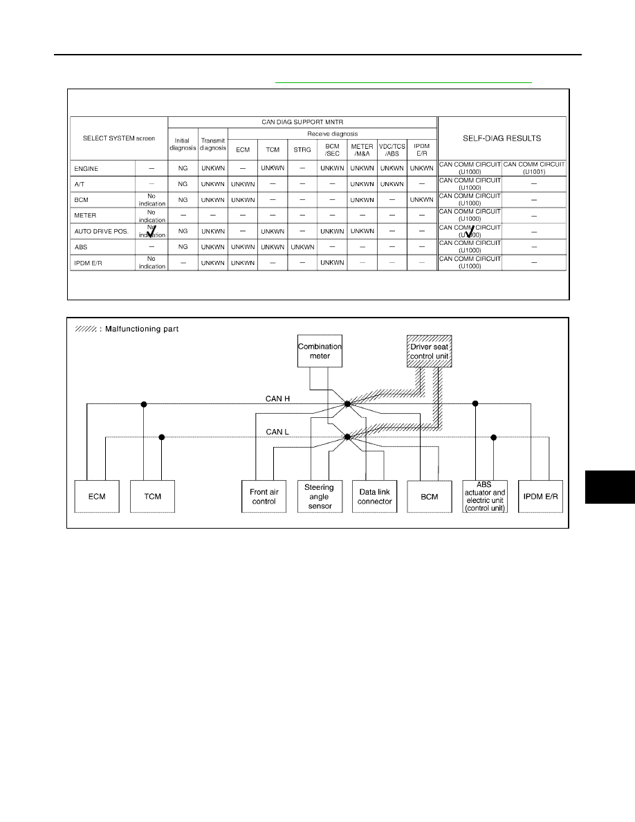
Case 9
Check driver seat control unit circuit. Refer to
LAN-115, "Driver Seat Control Unit Circuit Inspection"
.
PKIB5104E
PKIB5229E