Nissan Pathfinder (2005 year). Manual - part 285
 

  Index      Manuals     Nissan Pathfinder (2005 year) - Service and Repair Manual


Search            copyright infringement  


Content      ..     283      284      285      286     ..


Nissan Pathfinder (2005 year). Manual - part 285


IDX-5

A

C

D

E

F

G

H

I

J

K

L

B

IDX

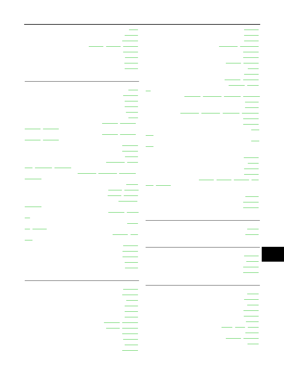
ALPHABETICAL INDEX

Gauges ..................................................................

DI-4

Generator ..........................................................

SC-19

Generic scan tool (GST) .................................

EC-139

Glass .....................................

GW-11

,

GW-44

,

GW-48

Glove box lamp ................................................

LT-149

GPS antenna .....................................................

AV-70

Grease ..............................................................

MA-11

Ground distribution ............................................

PG-29

H

H/LAMP - Wiring diagram ....................................

LT-8

Handling precautions for plastics .....................

BL-151

Harness connector ............................................

PG-71

Harness layout ..................................................

PG-39

Hazard warning lamp .........................................

LT-74

Headlamp .............................................................

LT-5

Heated oxygen sensor 2 (bank 1) ....

EC-224

,

EC-234

,

EC-436

,

EC-448

Heated oxygen sensor 2 (bank 2) ....

EC-224

,

EC-234

,

EC-436

,

EC-448

Heated oxygen sensor 2 heater (bank 1) ........

EC-174

Heated oxygen sensor 2 heater (bank 2) ........

EC-174

Heated seat .......................................................

SE-85

Heater and cooling unit (Heater core) .

ATC-133

,

ATC-

137

,

MTC-86

,

MTC-88

Heater unit (heater core)

ATC-133

,

ATC-137

,

MTC-86

,

MTC-88

Height (Dimensions) ...........................................

GI-49

HFC134a (R134a) system identification

ATC-7

,

MTC-6

HFC134a (R134a) system precaution ..

ATC-5

,

MTC-4

HFC134a (R134a) system service procedure

ATC-151

,

MTC-97

HFC134a (R134a) system service tools

ATC-14

,

MTC-

12

HFC134a system service equipment precaution

ATC-

11

,

MTC-9

High & low reverse clutch solenoid valve .

AT-156

,

AT-

158

Homelink universal transceiver ........................

BL-118

Horn ................................................................

WW-56

HORN - Wiring diagram ..................................

WW-56

How to erase DTC for OBD system ..................

EC-61

HSEAT - Wiring diagram ...................................

SE-87

I

I/MIRR - Wiring diagram ...................................

GW-55

IATS - Wiring diagram .....................................

EC-201

Identification plate ..............................................

GI-47

Idle air volume learning .....................................

EC-89

Idle mixture ratio ................................................

EC-77

Idle speed ..........................................................

EC-77

Idle speed control (ISC) ....................

EC-387

,

EC-389

Ignition coil ..........................................

EM-31

,

EC-657

Ignition control system ....................................

EC-657

Ignition key hole illumination ............................

LT-129

Ignition timing ....................................................

EC-77

IGNSYS - Wiring diagram ...............................

EC-658

ILL - Wiring diagram .........................................

LT-154

Illumination .......................................................

LT-148

Illumination control ............................................

LT-162

In vehicle sensor ...........................

ATC-116

,

ATC-126

INJECT - Wiring diagram .................................

EC-680

Injector .............................................................

EC-679

Input clutch solenoid valve .................

AT-144

,

AT-146

Instrument panel ..................................................

IP-10

INT/L - Wiring diagram .....................................

LT-135

Intake air temperature sensor ............

EC-199

,

EC-219

Intake door control linkage adjustment .

ATC-74

,

MTC-

54

Intake door motor

ATC-72

,

ATC-140

,

MTC-53

,

MTC-89

Intake manifold ..................................................

EM-19

Intake manifold collector ....................................

EM-16

Intake sensor ..

ATC-122

,

ATC-128

,

MTC-79

,

MTC-82

Intake valve timing control (Bank 1) ................

EC-170

Intake valve timing control (Bank 2) ................

EC-170

Intake valve timing control solenoid valve (Bank 1)

EC-

411

Intake valve timing control solenoid valve (Bank 2)

EC-

411

Integrated homelink transmitter - See Homelink univer-
sal tranceiver ....................................................

BL-118

Interior .................................................................

EI-27

Interior lamp ......................................................

LT-129

Interior lamp on-off control ................................

LT-130

Internal gear (Transfer) ..

TF-149

,

TF-176

,

TF-276

,

TF-

278

,

TF-284

IPDM (Intelligent power distribution module engine
room) .................................................................

PG-17

IVCB1 - Wiring diagram ...................................

EC-412

IVCB2 - Wiring diagram ...................................

EC-414

J

Jacking points .....................................................

GI-40

Junction box (J/B) ..............................................

PG-79

K

Key illumination ................................................

LT-130

KEYLES - Wiring diagram ..................................

BL-46

Knock sensor (KS) ...........................................

EC-293

KS - Wiring diagram ........................................

EC-294

L

Length (Dimensions) ..........................................

GI-49

License lamp ....................................................

LT-102

Lifting points .......................................................

GI-41

Line pressure solenoid valve ...........................

AT-123

Line pressure switch (Transfer) ........................

TF-167

Line pressure test (A/T) .....................................

AT-51

Liquid gasket application ................

EM-5

,

LU-2

,

CO-2

Location of electrical units .................................

PG-67

Low coast brake solenoid valve ..........

AT-160

,

AT-162

Low tire pressure warning system ......................

WT-7

Low tire pressure warning system - trouble diagnoses

IDX-6

ALPHABETICAL INDEX

WT-10

Low tire pressure warning system - Wiring diagram .....

WT-10

Lubricant (R134a) A/C ......................

ATC-22

,

MTC-19

Lubricants .........................................................

MA-11

Lubrication circuit (engine) ...................................

LU-4

Lubrication oil A/C .............................

ATC-22

,

MTC-19

Lubrication-locks, hinges and hood latches ......

MA-33

M

MAFS - Wiring diagram .....................

EC-186

,

EC-194

Magnet clutch .

ATC-96

,

ATC-156

,

MTC-63

,

MTC-101

MAIN - Wiring diagram ....................................

EC-159

Main oil pump (Transfer) ..................................

TF-167

Mainshaft (Transfer)

TF-167

,

TF-276

,

TF-278

,

TF-284

Maintenance (engine)Schedule 1 .......................

MA-7

Maintenance (engine)Schedule 2 .......................

MA-9

Major overhaul (Final drive) ..............

FFD-16

,

RFD-16

Major overhaul (Transfer) ...................

TF-146

,

TF-276

Malfunction indicator lamp (MIL) ........................

EC-62

Map lamp ..........................................................

LT-130

Mass air flow sensor (MAFS) .............

EC-183

,

EC-192

Meter .....................................................................

DI-4

METER - Wiring diagram ......................................

DI-8

MIL data link connectors circuit .......................

EC-707

MIL/DL - Wiring diagram ..................................

EC-707

MIRROR - Wiring diagram ................................

GW-78

Misfire ..............................................................

EC-284

Mode door control linkage adjustment ..

ATC-61

,

MTC-

46

Mode door motor

ATC-59

,

ATC-141

,

MTC-45

,

MTC-90

Model variation ...................................................

GI-46

Multiport fuel injection (MFI) system ..................

EC-25

Multiport fuel injection precautions .......................

GI-5

Multi-remote control system - See Remote keyless entry
system ...............................................................

BL-40

N

NATS - Wiring diagram ....................................

BL-102

NAVI - Wiring diagram .......................................

AV-87

NAVI Control Unit ............................................

AV-165

Neutral-4LO switch ............................................

TF-65

NVH troubleshooting (AX) .................................

FAX-4

NVH troubleshooting (EM) ................................

EM-10

NVH troubleshooting (Final drive) .........

FFD-6

,

RFD-7

NVH troubleshooting (Propeller shaft) .................

PR-3

NVH troubleshooting (RAX) ..............................

RAX-4

NVH troubleshooting (RSU) ..............................

RSU-4

NVH troubleshooting (ST) ....................................

PS-5

NVH troubleshooting (Transfer) ............

TF-12

,

TF-192

NVH troubleshooting (WT)NVH troubleshooting (WT) .

WT-3

NVIS (Nissan vehicle immobilizer system) ........

BL-99

O

O2H2B1 - Wiring diagram ................................

EC-176

O2H2B2 - Wiring diagram ...............................

EC-178

O2S2B1 - Wiring diagram ..

EC-226

,

EC-237

,

EC-439

,

EC-451

O2S2B2 - Wiring diagram ..

EC-228

,

EC-239

,

EC-441

,

EC-453

Oil cooler (engine) ..............................................

LU-10

Oil filter .................................................................

LU-9

Oil filter (Transfer) ............................................

TF-143

Oil pan (engine) ................................................

EM-26

Oil pressure (engine) ...........................................

LU-7

Oil pump (A/T) ..................................................

AT-281

Oil pump (engine) ..............................................

LU-12

Oil pump regulator valve (engine) ......................

LU-12

Oil seal replacement (engine) ...........................

EM-88

Oil seal replacement (front of final drive)

FFD-9

,

RFD-

10

Oil seal replacement (side of final drive)

FFD-12

,

RFD-

12

On board diagnostic system .............................

EC-48

ORVR (On-board Refueling Vapor Recovery) ..

EC-40

Overheat .........................................................

EC-463

Oversize piston ...............................................

EM-126

P

P/SCKT - Wiring diagram .................................

WW-54

Pantograph jack ..................................................

GI-40

Park/Neutral position switch ............................

EC-615

Park/neutral position switch (A/T) ....................

AT-108

Parking brake control ...........................................

PB-4

PCV (positive crankcase ventilation) ................

EC-45

Personal lamp ..................................................

LT-130

PGC/V - Wiring diagram ...................

EC-334

,

EC-557

PHSB1 - Wiring diagram .................................

EC-307

PHSB2 - Wiring diagram .................................

EC-309

Pilot bushing replacement - See Pilot converter ...

EM-

107

Piston assembly ..............................................

EM-117

Piston pin inspection .......................................

EM-122

Piston ring inspection ......................................

EM-123

Piston to bore clearance .................................

EM-126

Planetary carrier (Transfer) ..

TF-149

,

TF-176

,

TF-276

,

TF-278

,

TF-284

,

TF-292

PNP/SW - Wiring diagram ..............................

EC-617

POS - Wiring diagram .....................................

EC-300

POWER - Wiring diagram ...................................

PG-6

Power door lock .................................................

BL-16

Power door mirror ............................................

GW-78

Power seat .........................................................

SE-81

Power steering fluid level ..................................

MA-31

Power steering gear ...........................................

PS-15

Power steering oil pump ....................................

PS-20

Power steering pressure (PSP) sensor ...........

EC-391

Power steering system bleeding ..........................

PS-6

Power supply routing ..........................................

PG-4

Power window ..................................................

GW-15

PRE/SE - Wiring diagram .................

EC-351

,

EC-357

Precautions (General) ...........................................

GI-3

Precautions in repairing high strength steel .....

BL-154

IDX-7

A

C

D

E

F

G

H

I

J

K

L

B

IDX

ALPHABETICAL INDEX

Pressure switch 1 ...............................

AT-150

,

AT-164

Pressure switch 2 .............................................

AT-162

Pressure switch 3 ...............................

AT-146

,

AT-166

Pressure switch 5 ...............................

AT-154

,

AT-168

Pressure switch 6 ...............................

AT-158

,

AT-170

Pressure test (A/T) .............................................

AT-51

Propeller shaft ...........................................

PR-4

,

PR-9

Propeller shaft inspection ..................................

MA-27

Propeller shaft on vehicle service .......................

PR-9

Propeller shaft vibration ............................

PR-4

,

PR-9

PS/SEN - Wiring diagram ................................

EC-392

R

Radiator .............................................................

CO-11

Radio - See Audio ...............................................

AV-6

Rear axle ...........................................................

RAX-5

Rear bumper .......................................................

EI-15

Rear case (Transfer)

TF-148

,

TF-181

,

TF-276

,

TF-278

,

TF-284

Rear combination lamp removal and installation ...

LT-

120

Rear cover packing replacement diff. ..............

FFD-13

Rear door .............................................

BL-89

,

GW-48

Rear seat ...........................................................

SE-96

Rear seat belt ......................................................

SB-5

Rear suspension ...............................................

RSU-5

Rear washer ....................................................

WW-37

Rear window defogger .....................................

GW-58

Rear wiper .......................................................

WW-37

Refrigerant connection precaution .......

ATC-7

,

MTC-6

Refrigerant discharging evacuating charging

ATC-151

,

MTC-97

Refrigerant general precaution .............

ATC-6

,

MTC-5

Refrigerant lines

ATC-151

,

ATC-159

,

ATC-160

,

MTC-

97

,

MTC-104

,

MTC-105

Refrigerant pressure sensor .

EC-691

,

ATC-101

,

ATC-

162

,

MTC-68

,

MTC-105

Relay box ..........................................................

PG-81

Remote keyless entry system ............................

BL-40

Removal and installation (A/T) ...........

AT-245

,

AT-249

Removal and installation (Transfer) ...

TF-145

,

TF-275

Revolution sensor (A/T) ...................................

AT-112

Road wheel size .................................................

GI-49

Rocker cover .....................................................

EM-40

Room lamp .......................................................

LT-129

Room lamp - See Interior lamp ........................

LT-129

ROOM/L - Wiring diagram ................................

LT-135

RP/SEN - Wiring diagram ...............................

EC-692

S

SAE J1979 - Servise $01 - 09 ...........................

EC-48

SEAT - Wiring diagram .........................

SE-81

,

SE-82

Seat belt inspection .................................

SB-9

,

MA-34

Seat belt pre-tensioner ....................................

SRS-58

Seat belt pre-tensioner disposal ......................

SRS-61

Seat belt, front .....................................................

SB-3

Seat belt, rear ......................................................

SB-5

Seat, front ..........................................................

SE-90

Seat, rear ...........................................................

SE-96

Self-diagnosis (Transfer) ......................

TF-53

,

TF-216

SEN/PW - Wiring diagram ...............................

EC-479

SHIFT - Wiring diagram ...................................

AT-224

Shift control (Transfer) ...

TF-149

,

TF-176

,

TF-276

,

TF-

278

,

TF-284

,

TF-298

Shift lock system ..............................................

AT-223

Shock absorber (front) .......................................

FSU-9

Shock absorber (rear) .....................................

RSU-13

Side air bag .....................................................

SRS-53

Side air bag (satellite) sensor ..........................

SRS-57

Side curtain air bag ..........................................

SRS-54

Side trim ..............................................................

EI-27

SMJ (super multiple junction) ............................

PG-77

Spare tire size .....................................................

GI-49

Spark plug .........................................................

EM-32

Spark plug replacement .....................................

MA-19

Specification value ...........................................

EC-148

Speedometer ........................................................

DI-4

Spiral cable ......................................................

SRS-47

SROOF - Wiring diagram ..................................

RF-13

SRS - See Supplemental Restraint System ......

SRS-6

SRS - Wiring diagram ......................................

SRS-13

SRS Trouble diagnoses .....................................

SRS-9

Stabilizer bar (front) .........................................

FSU-11

Stabilizer bar (rear) .........................................

RSU-20

Stall test (A/T) ....................................................

AT-50

Standardized relay .............................................

PG-75

START - Wiring diagram ...................................

SC-11

Starting system ..................................................

SC-10

Steering gear, linkage and transfer gear inspection .....

MA-31

Steering linkage .................................................

PS-15

Steering wheel and column .................................

PS-8

Step lamp .........................................................

LT-130

Stop lamp ...........................................................

LT-97

Stop lamp switch .............................................

EC-625

STOP/L - Wiring diagram ...................................

LT-98

Strut (front) ........................................................

FSU-9

Sub-oil pump (Transfer) ....................................

TF-167

Sun gear (Transfer)

TF-149

,

TF-176

,

TF-276

,

TF-278

,

TF-284

Sun roof, electric ................................................

RF-10

Sunload sensor ..............................................

ATC-120

Sunroof ..............................................................

RF-25

Supplemental Restraint System ........................

SRS-6

Symbols and abbreviations .......................

GI-9

,

GI-22

Symptom matrix chart ......................................

EC-102

System readiness test (SRT) code ....................

EC-54

T

T/TOW - Wiring diagram ...................................

LT-125

Tachometer ..........................................................

DI-4

Tail lamp ...........................................................

LT-102

TAIL/L - Wiring diagram ....................................

LT-105

TCM circuit diagram ..........................................

AT-49

TCM inspection table .........................................

AT-83

IDX-8

ALPHABETICAL INDEX

TCS - Wiring diagram ......................

BRC-17

,

BRC-79

TCS (traction control system) ............

BRC-8

,

BRC-69

TCS component parts and connector location

BRC-15

,

BRC-77

TCS wheel sensors ..........................

BRC-15

,

BRC-77

Theft warning system - See Vehicle security (Theft warn-
ing) system ........................................................

BL-68

Thermometer ......................................................

DI-27

Thermostat ........................................................

CO-21

Three way catalyst ............................................

EM-21

Three way catalyst function (Bank 1) ...............

EC-314

Three way catalyst function (Bank 2) ...............

EC-314

Three way catalyst precautions ............................

GI-5

Throttle control motor .......................................

EC-431

Throttle control motor relay ..............................

EC-426

Throttle position sensor (TPS) ..

EC-209

,

EC-277

,

EC-

474

,

EC-476

,

EC-643

Tie-rod ...............................................................

PS-15

Timing chain .....................................................

EM-54

Tire rotation .......................................................

MA-29

Tire size ..............................................................

GI-49

Torque converter installation

AT-247

,

AT-248

,

AT-251

Torque convertor clutch solenoid valve ...

AT-119

,

AT-

121

Tow truck towing .................................................

GI-42

Towing point .......................................................

GI-43

TPS1 - Wiring diagram ....................................

EC-279

TPS2 - Wiring diagram ....................................

EC-211

TPS3 - Wiring diagram ....................................

EC-645

Traction control system - Wiring diagram ......

BRC-17

,

BRC-79

Transfer control device

TF-79

,

TF-83

,

TF-140

,

TF-243

,

TF-272

Transfer control unit inspection table ....

TF-38

,

TF-210

Transfer dropping resistor ..................................

TF-92

Transfer fluid temperature sensor .......

TF-106

,

TF-167

Transfer motor ....................................

TF-104

,

TF-142

Transfer motor relay ........................................

TF-104

Transfer oil replacement ...................................

MA-25

Transfer serial number ........................................

GI-48

Transmission serial number ................................

GI-48

Tread-FR&RR (Dimensions) ...............................

GI-49

Trim .....................................................................

EI-27

TRNSCV - Wiring diagram ...............................

BL-118

Trouble diagnoses ................................................

GI-9

Turbine revolution sensor ................................

AT-135

TURN - Wiring diagram ......................................

LT-77

Turn signal lamp .................................................

LT-74

Two trip detection logic ......................................

EC-48

Two-pole lift ........................................................

GI-41

V

Vacuum hose (brake system) ............................

BR-21

Vacuum hose drawing (Engine control) ...........

EC-113

Valve clearance ................................................

EM-83

Valve guide ...........................................

EM-98

,

EM-99

Valve lifter .........................................................

EM-78

Valve seat .......................................................

EM-100

Valve spring ......................................

EM-101

,

EM-102

Vanity mirror lamp ............................................

LT-129

Variable induction air control system (VIAS) ..

EC-620

,

EC-670

VDC (vehicle dynamics control) .........

BRC-8

,

BRC-69

VDC -Wiring diagram .......................

BRC-17

,

BRC-79

Vehicle identification number ..............................

GI-47

Vehicle recovery (freeing a stuck vehicle) ..........

GI-43

Vehicle security (theft warning) system .............

BL-68

Vehicle speed sensor (VSS) ...........................

EC-385

VEHSEC - Wiring diagram .................................

BL-73

VENT/V - Wiring diagram ..................

EC-341

,

EC-565

VIAS - Wiring diagram ....................................

EC-672

VIAS/V - Wiring diagram .................................

EC-621

Video Monitor .....................................................

AV-68

VIN registration .................................................

EC-88

Viscosity number (SAE) ....................................

MA-12

W

W/ANT - Wiring diagram ....................................

AV-57

Wait detection switch ............................

TF-72

,

TF-236

WARN - Wiring diagram ......................................

DI-34

Warning chime ....................................................

DI-46

Warning lamps ....................................................

DI-33

Washer, front .....................................................

WW-4

Washer, rear ....................................................

WW-37

Water pump ......................................................

CO-16

Water temperature gauge .....................................

DI-4

Wheel alignment (front) .....................................

FSU-6

Wheel alignment (rear) .....................................

RSU-6

Wheel balance ..................................................

MA-29

Wheel bearing (front) ........................................

FAX-5

Wheel bearing (rear) .........................................

RAX-5

Wheel hub (rear) ...............................................

RAX-5

Wheel size ..........................................................

GI-49

Wheelbase (Dimensions) ....................................

GI-49

Width (Dimensions) .............................................

GI-49

WINDOW - Wiring diagram ..............................

GW-21

Window antenna ................................................

AV-56

Window, door ......................................

GW-44

,

GW-48

Windshield .......................................................

GW-11

WIP/R - Wiring diagram ...................................

WW-39

WIPER - Wiring diagram ..................................

WW-11

Wiper, front ........................................................

WW-4

Wiper, rear .......................................................

WW-37

Wiring Diagram (Cell code) list .........................

PG-64

Wiring diagrams ..................................................

GI-15

WT-T/WARN - Wiring diagram ..........................

WT-10

IP-1

INSTRUMENT PANEL

I BODY

CONTENTS

C

D

E

F

G

H

J

K

L

M

SECTION

A

B

IP

2005 Pathfinder

PRECAUTIONS .......................................................... 2

Precautions for Supplemental Restraint System
(SRS) “AIR BAG” and “SEAT BELT PRE-TEN-
SIONER” .................................................................. 2

PREPARATION ........................................................... 3

Special Service Tools ............................................... 3
Commercial Service Tools ........................................ 3

SQUEAK AND RATTLE TROUBLE DIAGNOSES..... 4

Work Flow ................................................................ 4

CUSTOMER INTERVIEW ..................................... 4
DUPLICATE THE NOISE AND TEST DRIVE ....... 5
CHECK RELATED SERVICE BULLETINS ........... 5
LOCATE THE NOISE AND IDENTIFY THE
ROOT CAUSE ...................................................... 5
REPAIR THE CAUSE ........................................... 5
CONFIRM THE REPAIR ....................................... 6

Generic Squeak and Rattle Troubleshooting ........... 6

INSTRUMENT PANEL .......................................... 6
CENTER CONSOLE ............................................. 6
DOORS ................................................................. 6

TRUNK .................................................................. 7
SUNROOF/HEADLINING ..................................... 7
OVERHEAD CONSOLE (FRONT AND REAR)..... 7
SEATS ................................................................... 7
UNDERHOOD ....................................................... 7

Diagnostic Worksheet ............................................... 8

INSTRUMENT PANEL ASSEMBLY ......................... 10

Removal and Installation ........................................ 10

INSTRUMENT PANEL ........................................ 10
CLUSTER LID C ................................................. 11
CLUSTER LID D ................................................. 12
LOWER INSTRUMENT PANEL LH ..................... 13
COMBINATION METER ...................................... 13
A/T FINISHER ..................................................... 13
LOWER INSTRUMENT PANEL RH AND GLOVE
BOX ..................................................................... 14
CENTER CONSOLE ........................................... 15

Disassembly and Assembly .................................... 16

CENTER CONSOLE ........................................... 16

IP-2

PRECAUTIONS

2005 Pathfinder

PRECAUTIONS

PFP:00001

Precautions for Supplemental Restraint System (SRS) “AIR BAG” and “SEAT
BELT PRE-TENSIONER”

EIS0044K

The Supplemental Restraint System such as “AIR BAG” and “SEAT BELT PRE-TENSIONER”, used along
with a front seat belt, helps to reduce the risk or severity of injury to the driver and front passenger for certain
types of collision. This system includes seat belt switch inputs and dual stage front air bag modules. The SRS
system uses the seat belt switches to determine the front air bag deployment, and may only deploy one front
air bag, depending on the severity of a collision and whether the front occupants are belted or unbelted.
Information necessary to service the system safely is included in the SRS and SB section of this Service Man-
ual.

WARNING:

To avoid rendering the SRS inoperative, which could increase the risk of personal injury or death
in the event of a collision which would result in air bag inflation, all maintenance must be per-
formed by an authorized NISSAN/INFINITI dealer.

Improper maintenance, including incorrect removal and installation of the SRS, can lead to per-
sonal injury caused by unintentional activation of the system. For removal of Spiral Cable and Air
Bag Module, see the SRS section.

Do not use electrical test equipment on any circuit related to the SRS unless instructed to in this
Service Manual. SRS wiring harnesses can be identified by yellow and/or orange harness connec-
tors.

PREPARATION

IP-3

C

D

E

F

G

H

J

K

L

M

A

B

IP

2005 Pathfinder

PREPARATION

PFP:00002

Special Service Tools

EIS0044L

The actual shapes of Kent-Moore tools may differ from those of special service tools illustrated here.

Commercial Service Tools

EIS0044M

Tool number
(Kent-Moore No.)
Tool name

Description

(J-39570)
Chassis ear

Locating the noise

(J-43980)
NISSAN Squeak and Rattle kit

Repairing the cause of noise

SBT839

SBT840

(Kent-Moore No.)
Tool name

Description

(J-39565)
Engine ear

Locating the noise

Power Tool

Loosening bolts and nuts

SIIA0995E

PBIC0191E

IP-4

SQUEAK AND RATTLE TROUBLE DIAGNOSES

2005 Pathfinder

SQUEAK AND RATTLE TROUBLE DIAGNOSES

PFP:00000

Work Flow

EIS0044N

CUSTOMER INTERVIEW

Interview the customer if possible, to determine the conditions that exist when the noise occurs. Use the Diag-
nostic Worksheet during the interview to document the facts and conditions when the noise occurs and any
customer's comments; refer to

IP-8, "Diagnostic Worksheet"

. This information is necessary to duplicate the

conditions that exist when the noise occurs.

The customer may not be able to provide a detailed description or the location of the noise. Attempt to
obtain all the facts and conditions that exist when the noise occurs (or does not occur).

If there is more than one noise in the vehicle, be sure to diagnose and repair the noise that the customer
is concerned about. This can be accomplished by test driving the vehicle with the customer.

After identifying the type of noise, isolate the noise in terms of its characteristics. The noise characteristics
are provided so the customer, service adviser and technician are all speaking the same language when
defining the noise.

Squeak —(Like tennis shoes on a clean floor)
Squeak characteristics include the light contact/fast movement/brought on by road conditions/hard sur-
faces = higher pitch noise/softer surfaces = lower pitch noises/edge to surface = chirping.

Creak—(Like walking on an old wooden floor)
Creak characteristics include firm contact/slow movement/twisting with a rotational movement/pitch
dependent on materials/often brought on by activity.

Rattle—(Like shaking a baby rattle)
Rattle characteristics include the fast repeated contact/vibration or similar movement/loose parts/missing
clip or fastener/incorrect clearance.

Knock —(Like a knock on a door)
Knock characteristics include hollow sounding/sometimes repeating/often brought on by driver action.

Tick—(Like a clock second hand)
Tick characteristics include gentle contacting of light materials/loose components/can be caused by driver
action or road conditions.

Thump—(Heavy, muffled knock noise)
Thump characteristics include softer knock/dead sound often brought on by activity.

Buzz—(Like a bumble bee)
Buzz characteristics include high frequency rattle/firm contact.

Often the degree of acceptable noise level will vary depending upon the person. A noise that you may
judge as acceptable may be very irritating to the customer.

Weather conditions, especially humidity and temperature, may have a great effect on noise level.

SBT842


Content      ..     283      284      285      286     ..