Index Manuals Nissan Pathfinder (2005 year) - Service and Repair Manual
Search copyright infringement
Content .. 275 276 277 278 ..
Nissan Pathfinder (2005 year). Manual - part 277
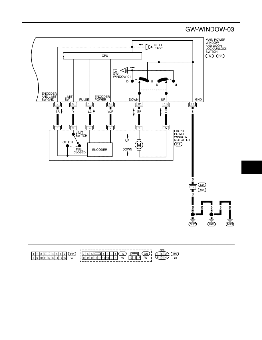
POWER WINDOW SYSTEM
GW-23
C
D
E
F
G
H
J
K
L
M
A
B
GW
2005 Pathfinder
WIWA0738E