Nissan Pathfinder (2005 year). Manual - part 267
2005
QUICK REFERENCE CHART PATHFINDER
Drive Belt Deflection and Tension
Spark Plugs (Double Platinum Tipped)
Front Wheel Alignment (Unladen*
1
)
ELS00112
*1: Fuel, radiator coolant and engine oil full. Spare tire, jack, hand tools and mats in designated positions.
*2: Target value 35
°
26
′
(35.43
°
)
*3: Target value 31
°
22
′
(31.37
°
)
*4: Target value 35
°
33
′
(35.55
°
)
*5: Target value 31
°
38
′
(31.63
°
)
Tension of drive belts
Auto adjustment by auto tensioner
Make
NGK
Standard type
PLFR5A-11
Hot type
PLFR4A-11
Cold type
PLFR6A-11
Gap (nominal)
1.1 mm (0.043 in)
Drive type
4x2
4x4
Camber
Degree minute (decimal degree)
Minimum
-0
°
15
′
(-0.25
°
)
0
°
0
′
(0.00
°
)
Nominal
0
°
15
′
(0.25
°
)
0
°
30
′
(0.50
°
)
Maximum
0
°
45
′
(0.75
°
)
1
°
00
′
(1.00
°
)
Cross camber
0
°
45
′
(0.75
°
) or less
0
°
45
′
(0.75
°
) or less
Caster
Degree minute (decimal degree)
Minimum
2
°
30
′
(2.50
°
)
2
°
15
′
(2.25
°
)
Nominal
3
°
0
′
(3.00
°
)
2
°
45
′
(2.75
°
)
Maximum
3
°
30
′
(3.50
°
)
3
°
15
′
(3.25)
Cross caster
0
°
45
′
(0.75
°
) or less
0
°
45
′
(0.75
°
) or less
Kingpin inclination
Degree minute (decimal degree)
Nominal
13
°
0
′
(13.00
°
)
12
°
45
′
(12.75
°
)
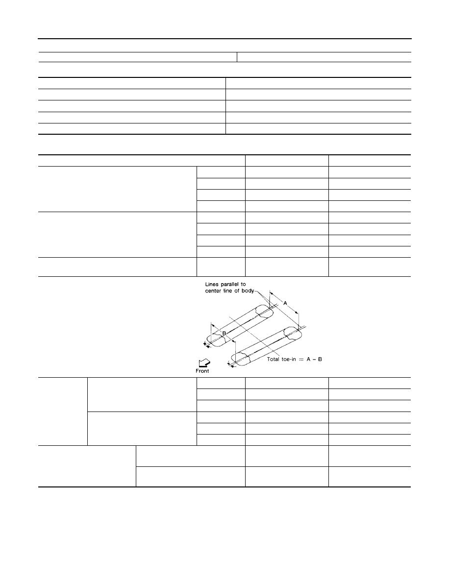
Total toe-in
Distance (A
−
B)
Minimum
2.1 mm (0.08 in)
2.1 mm (0.08 in)
Nominal
3.1 mm (0.12 in)
3.1 mm (0.12 in)
Maximum
4.1 mm (0.16 in)
4.1 mm (0.16 in)
Angle (left wheel or right wheel)
Degree minute (decimal degree)
Minimum
0
°
5
′
(0.08
°
)
0
°
5
′
(0.08
°
)
Nominal
0
°
7
′
(0.12
°
)
0
°
7
′
(0.12
°
)
Maximum
0
°
9
′
(0.15
°
)
0
°
9
′
(0.15
°
)
Wheel turning angle (full turn)
Inside
Degree minute (Decimal degree)
33
°
26
′
– 35
°
26
′
*
2
(33.43
°
– 35.43
°
)
33
°
33
′
– 35
°
33
′
*
4
(33.60
°
– 35.60
°
)
Outside
Degree minute (Decimal degree)
29
°
22
′
– 31
°
22
′
*
3
(29.37
°
– 31.37
°
)
29
°
38
′
– 31
°
38
′
*
5
(29.73
°
– 31.73
°
)
SFA234AC