Nissan Pathfinder (2005 year). Manual - part 208
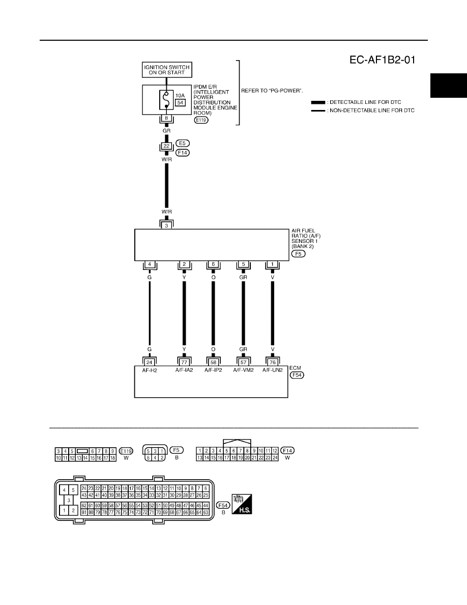
DTC P1274, P1284 A/F SENSOR 1
EC-515
C
D
E
F
G
H
I
J
K
L
M
A
EC
2005 Pathfinder
BANK 2
BBWA1731E
|
|
|
DTC P1274, P1284 A/F SENSOR 1 EC-515 C D E F G H I J K L M A EC
2005 Pathfinder BANK 2 BBWA1731E |