Nissan Pathfinder (2005 year). Manual - part 131
TROUBLE DIAGNOSES FOR SYMPTOMS
BRC-125
[HDC/HSA/VDC/TCS/ABS]
C
D
E
G
H
I
J
K
L
M
A
B
BRC
2005 Pathfinder
Stop Lamp Relay Inspection
EFS005BL
STOP LAMPS TURN ON THOUGH HDC DOES NOT FUNCTION
1.
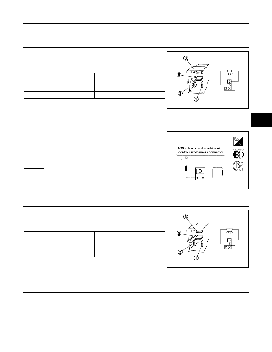
INSPECTION OF STOP LAMP RELAY
1.
Turn ignition switch OFF.
2.
Disconnect stop lamp relay connector E12.
3.
Check continuity between stop lamp relay terminals 3 and 5.
OK or NG
OK
>> GO TO 2.
NG
>> Replace stop lamp relay.
2.
INSPECTION OF STOP LAMP RELAY CIRCUIT
1.
Disconnect ABS actuator and electric unit (control unit) connec-
tor E125.
2.
Check continuity between ABS actuator and electric unit (control
unit) connector E125 terminal 13 and ground.
OK or NG
OK
>> Replace ABS actuator and electric unit (control unit).
Refer to
BRC-131, "Removal and Installation"
.
NG
>> Repair or replace harness or connector.
STOP LAMPS DO NOT TURN ON THOUGH HDC FUNCTIONS
1.
INSPECTION OF STOP LAMP RELAY
1.
Turn ignition switch OFF.
2.
Disconnect stop lamp relay connector E12.
3.
Check continuity between stop lamp relay terminals 3 and 5.
OK or NG
OK
>> Repair the stop lamp circuit.
NG
>> Replace stop lamp relay.
HDC Switch Inspection
EFS005BM
1.
HDC SWITCH INSPECTION
Check if the HDC indicator lamp in the combination meter turns on or flashes when pressing HDC switch.
OK or NG
OK
>> Inspection End.
NG
>> GO TO 2.
Condition
Continuity
12V direct current supply between
terminals 1 and 2
Yes
No current supply
No
SEF145X
Continuity should not exist.
WFIA0353E
Condition
Continuity
12V direct current supply between
terminals 1 and 2
Yes
No current supply
No
SEF145X