Nissan Pathfinder (2005 year). Manual - part 123


  Index      Manuals     Nissan Pathfinder (2005 year) - Service and Repair Manual


Search            copyright infringement  


Content      ..     121      122      123      124     ..


Nissan Pathfinder (2005 year). Manual - part 123


ACTUATOR AND ELECTRIC UNIT (ASSEMBLY)

BRC-61

[VDC/TCS/ABS]

C

D

E

G

H

I

J

K

L

M

A

B

BRC

2005 Pathfinder

ACTUATOR AND ELECTRIC UNIT (ASSEMBLY)

PFP:47660

Removal and Installation

EFS004NX

REMOVAL

1.

Disconnect the negative battery terminal.

2.

Drain the brake fluid. Refer to

BR-11, "Drain and Refill"

.

3.

Disconnect the actuator harness from the ABS actuator and electric unit (control unit).

CAUTION:

To remove the brake tubes, use a flare nut wrench to prevent the flare nuts and brake tubes from
being damaged.

Be careful not to splash brake fluid on painted areas.

4.

Disconnect the brake tubes.

5.

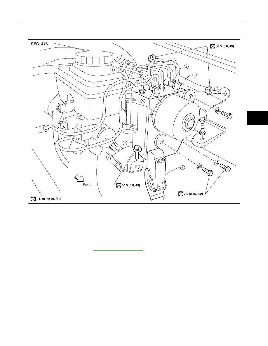
Remove the three bolts and remove the ABS actuator and electric unit (control unit).

LFIA0244E

1. To rear left

2. To rear right

3. To front left

4. To front right

5. From the master cylinder secondary side 6. From the master cylinder primary side

7. ABS actuator and electric unit (control
unit)

8. Harness connector

BRC-62

[VDC/TCS/ABS]

ACTUATOR AND ELECTRIC UNIT (ASSEMBLY)

2005 Pathfinder

INSTALLATION

Installation is in the reverse order of removal.

CAUTION:

To install, use a flare nut wrench (commercial service tool).

Always tighten brake tubes to specification when installing. Refer to

BR-13, "Hydraulic Circuit"

.

Never reuse drained brake fluid.

After installation of the ABS actuator and electric unit (control unit), refill brake system with new
brake fluid. Then bleed the air from the system. Refer to

BR-12, "Bleeding Brake System"

.

NOTE:
In the case that ABS actuator and electric unit (control unit) is replaced, make sure to adjust position of steer-
ing angle sensor. Refer to

BRC-57, "Adjustment of Steering Angle Sensor Neutral Position"

.

STEERING ANGLE SENSOR

BRC-63

[VDC/TCS/ABS]

C

D

E

G

H

I

J

K

L

M

A

B

BRC

2005 Pathfinder

STEERING ANGLE SENSOR

PFP:25554

Removal and Installation

EFS004NY

Refer to

SRS-47, "Removal and Installation"

.

NOTE:

The steering angle sensor is an integral part of the spiral cable.

In the case that the ABS actuator and electronic unit (control unit) is replaced, make sure to adjust posi-
tion of steering angle sensor. Refer to

BRC-57, "Adjustment of Steering Angle Sensor Neutral Position"

.

BRC-64

[VDC/TCS/ABS]

G SENSOR

2005 Pathfinder

G SENSOR

PFP:47930

Removal and Installation

EFS004NZ

REMOVAL

1.

Remove center console. Refer to

IP-15, "CENTER CONSOLE"

.

2.

Remove yaw rate/side/decel G sensor attaching nuts as shown.

The location of the sensor is the same for all models.

CAUTION:

Do not use power tools to remove or install yaw rate/side/
decel G sensor.

Do not drop or strike the yaw rate/side/decel G sensor.

3.

Disconnect harness connector and remove the yaw rate/side/
decel G sensor.

INSTALLATION

Installation is in the reverse order of removal.
NOTE:
After performing the above work, calibrate the yaw rate/side/decel G sensor. Refer to

BRC-57, "Calibration of

Yaw Rate/Side/Decel G Sensor"

.

WFIA0230E

PRECAUTIONS

BRC-65

[HDC/HSA/VDC/TCS/ABS]

C

D

E

G

H

I

J

K

L

M

A

B

BRC

2005 Pathfinder

PRECAUTIONS

PFP:00001

Precautions for Supplemental Restraint System (SRS) “AIR BAG” and “SEAT
BELT PRE-TENSIONER”

EFS005A4

The Supplemental Restraint System such as “AIR BAG” and “SEAT BELT PRE-TENSIONER”, used along
with a front seat belt, helps to reduce the risk or severity of injury to the driver and front passenger for certain
types of collision. Information necessary to service the system safely is included in the SRS and SB section of
this Service Manual.

WARNING:

To avoid rendering the SRS inoperative, which could increase the risk of personal injury or death
in the event of a collision which would result in air bag inflation, all maintenance must be per-
formed by an authorized NISSAN/INFINITI dealer.

Improper maintenance, including incorrect removal and installation of the SRS, can lead to per-
sonal injury caused by unintentional activation of the system. For removal of Spiral Cable and Air
Bag Module, see the SRS section.

Do not use electrical test equipment on any circuit related to the SRS unless instructed to in this
Service Manual. SRS wiring harnesses can be identified by yellow and/or orange harnesses or
harness connectors.

Precautions for Brake System

EFS005A5

CAUTION:

Refer to

MA-11, "RECOMMENDED FLUIDS AND LUBRICANTS"

for recommended brake fluid.

Never reuse drained brake fluid.

Be careful not to splash brake fluid on painted areas; it may cause paint damage. If brake fluid is
splashed on painted areas, wash it away with water immediately.

To clean or wash all parts of master cylinder and disc brake caliper, use clean brake fluid.

Never use mineral oils such as gasoline or kerosene. They will ruin rubber parts of the hydraulic
system.

Use flare nut wrench when removing and installing brake
tube.

If a brake fluid leak is found, the part must be disassembled
without fail. Then it has to be replaced with a new one if a
defect exists.

Turn the ignition switch OFF and remove the connector of
the ABS actuator and electric unit (control unit) or the bat-
tery terminal before performing the work.

Always torque brake lines when installing.

Burnish the brake contact surfaces after refinishing or
replacing rotors, after replacing pads, or if a soft pedal
occurs at very low mileage.
Refer to

BR-28, "BRAKE BURNISHING PROCEDURE"

(front disc brake) or

BR-34, "BRAKE BUR-

NISHING PROCEDURE"

(rear disc brake).

WARNING:

Clean brake pads and shoes with a waste cloth, then wipe with a dust collector.

Precautions When Using CONSULT-II

EFS005A6

When connecting CONSULT-II to data link connector, connect them through CONSULT-II CONVERTER.

CAUTION:

If CONSULT-II is used with no connection of CONSULT-II CONVERTER, malfunctions might be
detected in self-diagnosis depending on control unit which carries out CAN communication.

CHECK POINTS FOR USING CONSULT-II

1.

Has CONSULT-II been used without connecting CONSULT-II CONVERTER on this vehicle?

If YES, GO TO 2.

If NO, GO TO 5.

SBR686C

BRC-66

[HDC/HSA/VDC/TCS/ABS]

PRECAUTIONS

2005 Pathfinder

2.

Is there any indication other than indications relating to CAN communication system in the self-diagnosis
results?

If YES, GO TO 3.

If NO, GO TO 4.

3.

Based on self-diagnosis results unrelated to CAN communication, carry out the inspection.

4.

Malfunctions may be detected in self-diagnosis depending on control units carrying out CAN communica-
tion. Therefor, erase the self-diagnosis results.

5.

Diagnose CAN communication system. Refer to

LAN-24, "CAN COMMUNICATION"

.

Precautions for Brake Control

EFS005A7

During ABS operation, the brake pedal may vibrate lightly and a mechanical noise may be heard. This is
normal.

During HDC operation, a mechanical noise may be heard. This is normal.

Just after starting vehicle, the brake pedal may vibrate or a motor operating noise may be heard from
engine compartment. This is a normal status of operation check.

Stopping distance may be longer than that of vehicles without ABS when vehicle drives on rough, gravel,
or snow-covered (fresh, deep snow) roads.

When an error is indicated by ABS or another warning lamp, collect all necessary information from cus-
tomer (what symptoms are present under what conditions) and check for simple causes before starting
diagnosis. Besides electrical system inspection, check brake booster operation, brake fluid level, and fluid
leaks.

If incorrect tire sizes or types are installed on the vehicle or brake pads are not Genuine NISSAN parts,
stopping distance or steering stability may deteriorate.

If there is a radio, antenna or related wiring near control module, ABS function may have a malfunction or
error.

If aftermarket parts (car stereo, CD player, etc.) have been installed, check for incidents such as harness
pinches, open circuits or improper wiring.

If the following components are replaced with non-genuine components or modified, the VDC OFF indica-
tor lamp and SLIP indicator lamp may turn on or the VDC system may not operate properly. Components
related to suspension (shock absorbers, struts, springs, bushings, etc.), tires, wheels (exclude specified
size), components related to brake system (pads, rotors, calipers, etc.), components related to engine
(muffler, ECM, etc.), components related to body reinforcement (roll bar, tower bar, etc.).

Driving with broken or excessively worn suspension components, tires or brake system components may
cause the VDC OFF indicator lamp and the SLIP indicator lamp to turn on, and the VDC system may not
operate properly.

When the TCS or VDC is activated by sudden acceleration or sudden turn, some noise may occur. The
noise is a result of the normal operation of the TCS and VDC.

When driving on roads which have extreme slopes (such as mountainous roads) or high banks (such as
sharp curves on a freeway), the VDC may not operate normally, or the VDC warning lamp and the SLIP
indicator lamp may turn on. This is not a problem if normal operation can be resumed after restarting the
engine.

Sudden turns (such as spin turns, acceleration turns), drifting, etc. with VDC turned off may cause the yaw
rate/side G sensor to indicate a problem. This is not a problem if normal operation can be resumed after
restarting the engine.

If battery is removed or steering angle sensor is disconnected, power to steering angle sensor is lost and
the screen goes into steering angle sensor safe mode.

When screen goes into steering angle sensor safe mode, perform "Adjustment of Steering Angle Sensor
Neutral Position" with CONSUT-II and check that VDC OFF indicator turns off. Additionally, perform self-
diagnosis, check that only "Steering Angle Sensor Safe Mode" is shown for self-diagnostic result, and
then delete the memory. (If the self-diagnostic result shows an indication other than "Steering Angle Sen-
sor Safe Mode", repair the relevant part and restart self-diagnosis.) The steering angle sensor is released
and returns to normal condition by performing the above operation.

When checking, if only "Steering Angle Sensor Safe Mode" is shown in the self-diagnostic result and VDC
OFF indicator is off, delete history of malfunction. This happens when battery power supply is lost and the
screen goes into Steering Angle Sensor Safe Mode, and then screen returns to normal mode automati-

PRECAUTIONS

BRC-67

[HDC/HSA/VDC/TCS/ABS]

C

D

E

G

H

I

J

K

L

M

A

B

BRC

2005 Pathfinder

cally by driving the vehicle in a straight forward direction [for approximately 30 seconds at 20 km/h (12
MPH) or more] after power is supplied again.

NOTE:
VDC OFF indicator lamp is on when VDC OFF switch is on.

Precautions for CAN System

EFS005A8

Do not apply voltage of 7.0V or higher to terminal to be measured.

Maximum open terminal voltage of tester in use must be less than 7.0V.

Before checking harnesses, turn ignition switch OFF and disconnect battery negative cable.

Area to be repaired must be soldered and wrapped with tape.
Make sure that fraying of twisted wire is within 110 mm (4.33 in).

Do not make a bypass connection to repaired area. (If the circuit
is bypassed, characteristics of twisted wire will be lost.)

Wiring Diagrams and Trouble Diagnosis

EFS005A9

When you read wiring diagrams, refer to the following:

GI-15, "How to Read Wiring Diagrams"

.

PG-4, "POWER SUPPLY ROUTING CIRCUIT"

.

When you perform trouble diagnosis, refer to the following:

GI-11, "HOW TO FOLLOW TEST GROUPS IN TROUBLE DIAGNOSES"

.

GI-27, "How to Perform Efficient Diagnosis for an Electrical Incident"

.

PKIA0306E

PKIA0307E

BRC-68

[HDC/HSA/VDC/TCS/ABS]

PREPARATION

2005 Pathfinder

PREPARATION

PFP:00002

Special Service Tool

EFS005AA

The actual shapes of Kent-Moore tools may differ from those of special service tools illustrated here.

Commercial Service Tools

EFS005AB

Tool number
(Kent-Moore No.)
Tool name

Description

(J-45741)
ABS active wheel sensor tester

Checking operation of ABS active wheel
sensors

205-D002
(

)

Bearing replacer

Removing sensor rotor

ST30720000
(J-25405)
Drift

Installing rear sensor rotor
a: 77 mm (0.03 in) dia.
b: 55 mm (2.17 in) dia.

ST27863000
(—)
Drift

Installing rear sensor rotor
a: 75 mm (2.95 in) dia.
b: 62 mm (2.44 in) dia.

KV40104710
(—)
Drift

Installing rear sensor rotor
a: 76 mm (2.99 in) dia.
b: 68.5 mm (2.697 in) dia.

WFIA0101E

ZZA0700D

ZZA0701D

ZZA0832D

ZZA0832D

Tool name

Description

1. Flare nut crowfoot
2. Torque wrench

Removing and installing brake piping
a: 10 mm (0.39 in)/12 mm (0.47 in)

S-NT360


Content      ..     121      122      123      124     ..