Nissan Pathfinder (2005 year). Manual - part 121


  Index      Manuals     Nissan Pathfinder (2005 year) - Service and Repair Manual


Search            copyright infringement  


Content      ..     119      120      121      122     ..


Nissan Pathfinder (2005 year). Manual - part 121


TROUBLE DIAGNOSIS FOR SELF-DIAGNOSTIC ITEMS

BRC-45

[VDC/TCS/ABS]

C

D

E

G

H

I

J

K

L

M

A

B

BRC

2005 Pathfinder

3.

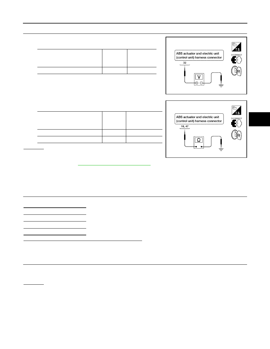
CHECKING SOLENOID POWER AND GROUND

1.

Check voltage between ABS actuator and electric unit (control
unit) harness connector E125 and body ground.

2.

Check resistance between ABS actuator and electric unit (con-
trol unit) harness connector E125 and body ground.

OK or NG

OK

>> Perform self-diagnosis again. If the same results

appear, replace ABS actuator and electric unit (control
unit). Refer to

BRC-61, "Removal and Installation"

.

NG

>> Repair the circuit.

Actuator Motor, Motor Relay, and Circuit Inspection

EFS004N9

INSPECTION PROCEDURE

1.

CHECKING SELF-DIAGNOSIS RESULTS

Check self-diagnosis results.

Is the above displayed in the self-diagnosis display items?

YES

>> GO TO 2.

NO

>> Inspection End.

2.

CONNECTOR INSPECTION

1.

Disconnect ABS actuator and electric unit (control unit) connector E125.

2.

Check the terminals for deformation, disconnection, looseness or damage.

OK or NG

OK

>> GO TO 3.

NG

>> Repair or replace as necessary.

ABS actuator and electric

unit (control unit)

harness connector E125

Body

ground

Measured

value

(Approx.)

32

12V

WFIA0195E

ABS actuator and electric

unit (control unit)

harness connector E125

Body

ground

Measured

value

(Approx.)

16

0

47

0

WFIA0196E

Self-diagnosis results

CONSULT-II display items

PUMP MOTOR

ACTUATOR RLY

BRC-46

[VDC/TCS/ABS]

TROUBLE DIAGNOSIS FOR SELF-DIAGNOSTIC ITEMS

2005 Pathfinder

3.

CHECKING ABS MOTOR AND MOTOR RELAY POWER SYSTEM

1.

Check voltage between ABS actuator and electric unit (control
unit) harness connector E125 and body ground.

2.

Check resistance between ABS actuator and electric unit (con-
trol unit) connector E125 and body ground.

OK or NG

OK

>> Perform self-diagnosis again. If the same results

appear, replace ABS actuator and electric unit (control
unit). Refer to

BRC-61, "Removal and Installation"

.

NG

>> Repair the circuit.

Stop Lamp Switch System Inspection

EFS004NA

INSPECTION PROCEDURE

1.

SELF-DIAGNOSIS RESULT CHECK

Check self-diagnosis results.

Is the above displayed in the self-diagnosis display items?

YES

>> GO TO 2.

NO

>> Inspection End.

2.

CONNECTOR INSPECTION

1.

Disconnect the ABS actuator and electric unit (control unit) connector E125 and stop lamp switch connec-
tor E38.

2.

Check the terminals for deformation, disconnection, looseness or damage.

OK or NG

OK

>> GO TO 3.

NG

>> Repair or replace as necessary.

ABS actuator and electric

unit (control unit)

harness connector E125

Body

ground

Measured

value

(Approx.)

1

12V

WFIA0209E

ABS actuator and electric

unit (control unit)

harness connector E125

Body

ground

Measured

value

(Approx.)

16

0

47

0

WFIA0196E

Self-diagnosis results

STOP LAMP SW

TROUBLE DIAGNOSIS FOR SELF-DIAGNOSTIC ITEMS

BRC-47

[VDC/TCS/ABS]

C

D

E

G

H

I

J

K

L

M

A

B

BRC

2005 Pathfinder

3.

STOP LAMP SWITCH INSPECTION

Check the voltage between the ABS actuator and electric unit (con-
trol unit) harness connector E125 terminal 41 and body ground.

OK or NG

OK

>> Perform self-diagnosis again. If the same results

appear, replace ABS actuator and electric unit (control
unit). Refer to

BRC-61, "Removal and Installation"

.

NG

>> Refer to

LT-97, "STOP LAMP"

.

ABS/TCS/VDC Control Unit Power and Ground Systems Inspection

EFS004NB

INSPECTION PROCEDURE

1.

SELF-DIAGNOSIS RESULT CHECK

Check self-diagnosis results.

Is the above displayed in the self-diagnosis display items?

YES

>> GO TO 2.

NO

>> Inspection End.

2.

CONNECTOR INSPECTION

1.

Disconnect the ABS actuator and electric unit (control unit) connector E125.

2.

Check the terminals for deformation, disconnection, looseness or damage.

OK or NG

OK

>> GO TO 3.

NG

>> Repair or replace as necessary.

3.

ABS/TCS/VDC CONTROL UNIT POWER AND GROUND CIRCUIT INSPECTION

Measure the voltage and continuity between the ABS actuator and electric unit (control unit) harness connec-
tor E125 and body ground.

OK or NG

OK

>> Check the battery for loose terminals, low voltage, etc. Repair as necessary.

NG

>> Repair the circuit.

Brake pedal depressed

: Battery voltage
(approx. 12V)

Brake pedal not depressed

: Approx. 0V

WFIA0198E

Self-diagnosis results

BATTERY VOLTAGE

Signal name

ABS actuator and electric unit

(control unit)

harness connector E125

Body

ground

Measured value

Power supply

1

Battery voltage (Approx. 12V)

32

Ground

16

Continuity should exist.

47

BRC-48

[VDC/TCS/ABS]

TROUBLE DIAGNOSIS FOR SELF-DIAGNOSTIC ITEMS

2005 Pathfinder

Brake Fluid Level Sensor System Inspection

EFS004NC

INSPECTION PROCEDURE

1.

SELF-DIAGNOSIS RESULT CHECK

1.

Check the brake reservoir tank fluid level. If the level is low, add brake fluid.

2.

Erase the self-diagnosis results and check the self-diagnosis results.

Is the above displayed in the self-diagnosis display items?

YES

>> GO TO 2.

NO

>> Inspection End.

2.

CONNECTOR INSPECTION

1.

Disconnect the ABS actuator and electric unit (control unit) connector E125 and brake fluid level switch
connector E21.

2.

Check the terminals for deformation, disconnection, looseness or damage.

OK or NG

OK

>> GO TO 3.

NG

>> Repair or replace as necessary.

3.

CHECK THE HARNESS BETWEEN THE BRAKE FLUID LEVEL SENSOR AND THE ABS ACTUATOR

AND ELECTRIC UNIT (CONTROL UNIT)

Check the continuity between the brake fluid level switch harness connector E21 and the ABS actuator and
electric unit (control unit) harness connector E125.

OK or NG

OK

>> Perform self-diagnosis again. If the same results appear, replace ABS actuator and electric unit

(control unit). Refer to

BRC-61, "Removal and Installation"

.

NG

>> Repair the circuit.

Pressure Sensor System Inspection

EFS004NF

INSPECTION PROCEDURE

1.

DISPLAY SELF DIAGNOSIS RESULTS

Check self-diagnosis result display item.

Is the self-diagnosis result display item shown above displayed?

YES

>> GO TO 2.

NO

>> Inspection End.

Self-diagnosis results

BR FLUID LEVEL LOW

ABS actuator and electric unit

(control unit) harness connector

E125

Brake fluid level switch harness

connector E21

Continuity

8

1

Yes

8

Ground

No

Ground

2

Yes

Self-diagnosis results

PRESS SEN CIRCUIT

TROUBLE DIAGNOSIS FOR SELF-DIAGNOSTIC ITEMS

BRC-49

[VDC/TCS/ABS]

C

D

E

G

H

I

J

K

L

M

A

B

BRC

2005 Pathfinder

2.

CONNECTOR INSPECTION

1.

Turn the ignition switch OFF.

2.

Disconnect the front pressure sensor connector E31 and ABS actuator and electric unit (control unit) con-
nector E125 and inspect the terminals for deformation, disconnection, looseness, or damage.

OK or NG

OK

>> GO TO 3.

NG

>> Repair connector.

3.

FRONT PRESSURE SENSOR CIRCUIT INSPECTION

1.

Measure the continuity between the ABS actuator and electric unit (control unit) harness connector E125
and front pressure sensor harness connector E31.

2.

Measure the continuity between the ABS actuator and electric unit (control unit) harness connector E125
and body ground.

OK or NG

OK

>> GO TO 4.

NG

>> Repair or replace harness or connector.

4.

FRONT PRESSURE SENSOR INSPECTION

1.

Reconnect the front pressure sensor and ABS actuator and electric unit (control unit) connectors.

2.

Use "DATA MONITOR" to check if the status of "PRESS SENSOR" is normal.

OK or NG

OK

>> Inspection End.

NG

>> Replace front pressure sensor.

Steering Angle Sensor Safe Mode Inspection

EFS005A0

INSPECTION PROCEDURE

1.

INDICATOR LAMP CHECK

Check that VDC OFF indicator lamp is on.

OK or NG

OK

>> GO TO 2.

NG

>> GO TO 3.

ABS actuator and electric unit (control

unit) harness connector E125

Front pressure sensor harness

connector E31

Continuity

18

3

Yes

19

1

20

2

ABS actuator and electric unit (control

unit) harness connector E125

Body ground

Continuity

18

No

19

20

Condition

Data monitor display (Approx.)

PRESS SENSOR

When brake pedal is depressed

Positive value

When brake pedal is released

0 bar

BRC-50

[VDC/TCS/ABS]

TROUBLE DIAGNOSIS FOR SELF-DIAGNOSTIC ITEMS

2005 Pathfinder

2.

ADJUSTMENT OF STEERING ANGLE SENSOR NEUTRAL POSITION

Adjust steering angle sensor neutral position. Refer to

BRC-57, "Adjustment of Steering Angle Sensor Neutral

Position"

.

OK or NG

OK

>> GO TO 3.

NG

>> Check steering angle sensor. Refer to

BRC-40, "Steering Angle Sensor System"

.

3.

INDICATOR LAMP CHECK

Check that VDC OFF indicator lamp is off.

OK or NG

OK

>> GO TO 4.

NG

>> Perform basic inspection. Refer to

BRC-24, "Basic Inspection"

.

4.

CHECK SELF-DIAGNOSTIC RESULTS

Perform ABS actuator and electric unit (control unit) self-diagnosis.

NOTE:
When self-diagnostic results show items other than those above, perform repair or replacement for the item
indicated and repeat self-diagnosis.
Is the above displayed on self-diagnosis display?

YES

>> Erase error memory.

NO

>> Inspection End.

CAN Communication System Inspection

EFS004NG

INSPECTION PROCEDURE

1.

CHECK CONNECTOR

1.

Turn ignition switch OFF, disconnect the ABS actuator and electric unit (control unit) connector, and check
the terminals for deformation, disconnection, looseness, and so on. If there is a malfunction, repair or
replace the terminal.

2.

Reconnect connector to perform self-diagnosis.

Is "CAN COMM CIRCUIT" displayed in self-diagnosis display items?

YES

>> Print out the self-diagnostic results, and refer to

LAN-24, "CAN COMMUNICATION"

.

NO

>> Connector terminal is loose, damaged, open, or shorted.

Inspection For Self-diagnosis Result "ST ANGLE SEN SIGNAL"

EFS004NH

INSPECTION PROCEDURE

1.

PERFORM SELF-DIAGNOSIS

Perform ABS actuator and electric unit (control unit) self-diagnosis.

Do self-diagnosis results indicate anything other than shown above?

YES

>> Perform repair or replacement for the item indicated.

NO

>> Perform adjustment of steering angle sensor neutral position. Refer to

BRC-57, "Adjustment of

Steering Angle Sensor Neutral Position"

. GO TO 2.

Self-diagnosis results

ST ANGL SEN SAFE

Self-diagnosis results

ST ANGLE SEN SIGNAL

TROUBLE DIAGNOSIS FOR SELF-DIAGNOSTIC ITEMS

BRC-51

[VDC/TCS/ABS]

C

D

E

G

H

I

J

K

L

M

A

B

BRC

2005 Pathfinder

2.

PERFORM SELF-DIAGNOSIS AGAIN

1.

Turn the ignition switch to OFF and then to ON and erase self-diagnosis results.

2.

Perform ABS actuator and electric unit (control unit) self-diagnosis again.

Are any self-diagnosis results displayed?

YES

>> Replace steering angle sensor. Refer to

BRC-63, "Removal and Installation"

.

NO

>> Inspection End.

Inspection For Self-diagnosis Result "DECEL G SEN SET"

EFS004NI

INSPECTION PROCEDURE

1.

PERFORM SELF-DIAGNOSIS

Perform ABS actuator and electric unit (control unit) self-diagnosis.

Do self-diagnosis results indicate anything other than shown above?

YES

>> Perform repair or replacement for the item indicated.

NO

>> Perform calibration of decel G sensor. Refer to

BRC-57, "Calibration of Yaw Rate/Side/Decel G

Sensor"

. GO TO 2.

2.

PERFORM SELF-DIAGNOSIS AGAIN

1.

Turn the ignition switch to OFF and then to ON and erase self-diagnosis results.

2.

Perform ABS actuator and electric unit (control unit) self-diagnosis again.

Are any self-diagnosis results displayed?

YES

>> Replace decel G sensor. Refer to

BRC-64, "Removal and Installation"

.

NO

>> Inspection End.

VDC OFF Indicator lamp Does Not Illuminate

EFS004NJ

INSPECTION PROCEDURE

1.

CHECK VDC OFF INDICATOR LAMP

Disconnect ABS actuator and electric unit (control unit) connector E125.

Do the ABS warning lamp and VDC OFF indicator lamp illuminate?

YES

>> Replace ABS actuator and electric unit (control unit). Refer to

BRC-61, "Removal and Installation"

.

NO

>> Replace combination meter. Refer to

IP-13, "COMBINATION METER"

.

Component Inspection

EFS004NK

VDC OFF SWITCH

Check the continuity between terminals 1 and 2.

Self-diagnosis results

DECEL G SEN SET

1 - 2

: Continuity should exist when pushing the
switch.
Continuity should not exist when releasing
the switch.

PFIA0307E

BRC-52

[VDC/TCS/ABS]

TROUBLE DIAGNOSES FOR SYMPTOMS

2005 Pathfinder

TROUBLE DIAGNOSES FOR SYMPTOMS

PFP:99999

ABS Works Frequently

EFS004NL

1.

CHECK WARNING LAMP ACTIVATION

Make sure warning lamp remains off while driving.

OK or NG

OK

>> GO TO 2.

NG

>> Carry out self-diagnosis. Refer to

BRC-30, "SELF-DIAGNOSIS"

.

2.

CHECK WHEEL SENSORS

Check the following.

Wheel sensor mounting for looseness

Wheel sensors for physical damage

Wheel sensor connectors for terminal damage or loose connections

Sensor rotor and mount for physical damage (rear only)

OK or NG

OK

>> GO TO 3.

NG

>> Repair or replace as necessary.

3.

CHECK FRONT AND REAR AXLES

Check front and rear axles for excessive looseness. Refer to

FAX-5, "WHEEL BEARING INSPECTION"

or

RAX-5, "WHEEL BEARING INSPECTION"

.

OK or NG

OK

>> GO TO 4.

NG

>> Repair as necessary.

4.

CHECK BRAKE FLUID PRESSURE

Check brake fluid pressure distribution.
Refer to

BRC-24, "Basic Inspection"

.

Is brake fluid pressure distribution normal?

YES

>> Inspection End.

NO

>> Perform Basic Inspection. Refer to

BRC-24, "Basic Inspection"

.


Content      ..     119      120      121      122     ..