Nissan Pathfinder (2005 year). Manual - part 119


  Index      Manuals     Nissan Pathfinder (2005 year) - Service and Repair Manual


Search            copyright infringement  


Content      ..     117      118      119      120     ..


Nissan Pathfinder (2005 year). Manual - part 119


TROUBLE DIAGNOSIS

BRC-29

[VDC/TCS/ABS]

C

D

E

G

H

I

J

K

L

M

A

B

BRC

2005 Pathfinder

CONSULT-II Function (ABS)

EFS004N2

CONSULT-II can display each diagnostic item using the diagnostic test modes shown following.

CONSULT-II BASIC OPERATION PROCEDURE
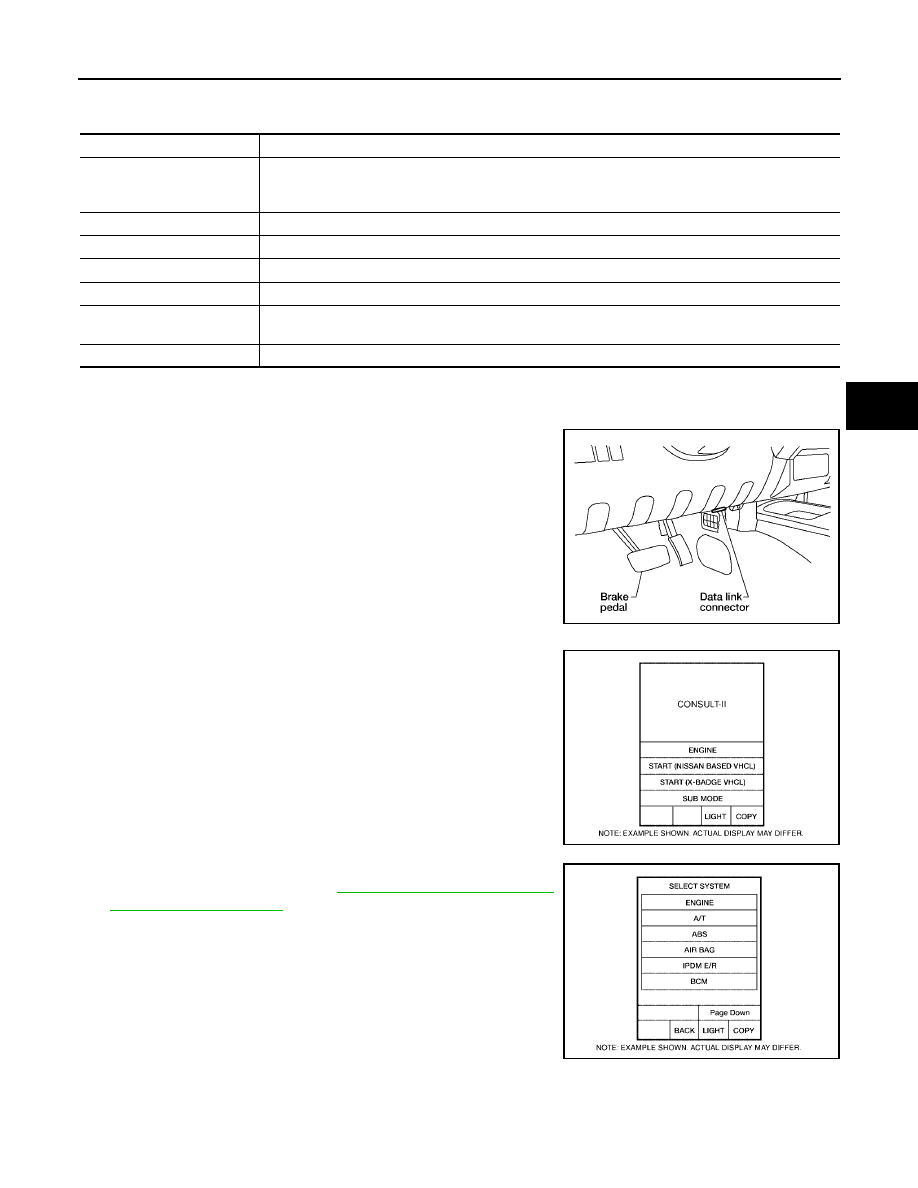
1.

Turn ignition switch OFF.

2.

Connect CONSULT-II and CONSULT-II CONVERTER to the
data link connector.

CAUTION:

If CONSULT-II is used with no connection of CONSULT-II
CONVERTER, malfunctions might be detected in self-diag-
nosis depending on control unit which carries out CAN
communication.

3.

Turn ignition switch ON.

4.

Touch “START (NISSAN BASED VHCL)”.

5.

Touch “ABS” in the “SELECT SYSTEM” screen.
If “ABS” is not indicated, go to

GI-38, "CONSULT-II Data Link

Connector (DLC) Circuit"

.

6.

Select the required diagnostic location from the “SELECT DIAG MODE” screen.
For further information, see the CONSULT-II Operation Manual.

ABS diagnostic mode

Description

WORK SUPPORT

Supports inspection and adjustments. Commands are transmitted to the ABS actuator and electric
unit (control unit) for setting the status suitable for required operation, input/output signals are
received from the ABS actuator and electric unit (control unit) and received data is displayed.

SELF-DIAG RESULTS

Displays ABS actuator and electric unit (control unit) self-diagnosis results.

DATA MONITOR

Displays ABS actuator and electric unit (control unit) input/output data in real time.

CAN DIAG SUPPORT MNTR

The result of transmit/receive diagnosis of CAN communication can be read.

ACTIVE TEST

Operation of electrical loads can be checked by sending drive signal to them.

FUNCTION TEST

Conducted by CONSULT-II instead of a technician to determine whether each system is "OK" or
"NG".

ECU PART NUMBER

ABS actuator and electric unit (control unit) part number can be read.

BBIA0538E

BCIA0029E

BCIA0030E

BRC-30

[VDC/TCS/ABS]

TROUBLE DIAGNOSIS

2005 Pathfinder

SELF-DIAGNOSIS
Description

If an error is detected in the system, the ABS warning lamp will turn on. In this case, perform self-diagnosis as
follows:

Operation Procedure

1.

Turn ignition switch OFF.

2.

Connect CONSULT-II and CONSULT-II CONVERTER to the data link connector.

CAUTION:

If CONSULT-II is used with no connection of CONSULT-II CONVERTER, malfunctions might be
detected in self-diagnosis depending on control unit which carries out CAN communication.

3.

Turn ignition switch ON.

4.

Start engine and drive at approximately 30 km/h (19 MPH) or more for approximately 1 minute.

5.

After stopping the vehicle, with the engine running, touch “START (NISSAN BASED VHCL)”, “ABS”,
“SELF-DIAG RESULTS” in order on the CONSULT-II screen.

CAUTION:

If “START (NISSAN BASED VHCL)” is touched immediately after starting the engine or turning on
the ignition switch, “ABS” might not be displayed in the SELECT SYSTEM screen. In this case,
repeat the operation from step 1.

6.

The self-diagnostic results are displayed. (If necessary, the self-diagnostic results can be printed out by
touching “PRINT”.)

When “NO DTC IS DETECTED” is displayed, check the ABS warning lamp, SLIP indicator lamp and
VDC OFF indicator lamp.

7.

Conduct the appropriate inspection from the display item list, and repair or replace the malfunctioning
component.

8.

Start engine and drive at approximately 30 km/h (19 MPH) or more for approximately 1 minute.

CAUTION:

When a wheel sensor “short-circuit” is detected, if the vehicle is not driven at 30 km/h (19 MPH)
for at least 1 minute, the ABS warning lamp will not turn off even if the malfunction is repaired.

9.

Turn ignition switch OFF to prepare for erasing the memory.

10. Start the engine and touch “START (NISSAN BASED VHCL)”, “ABS”, “SELF-DIAG RESULTS”, “ERASE”

in order on the CONSULT-II screen to erase the error memory.
If “ABS” is not indicated, go to

GI-38, "CONSULT-II Data Link Connector (DLC) Circuit"

.

CAUTION:

If the error memory is not erased, re-conduct the operation from step 5.

11. For the final inspection, drive at approximately 30 km/h (19 MPH) or more for approximately 1 minute and

confirm that the ABS warning lamp, SLIP indicator lamp, and VDC OFF indicator lamp are off.

TROUBLE DIAGNOSIS

BRC-31

[VDC/TCS/ABS]

C

D

E

G

H

I

J

K

L

M

A

B

BRC

2005 Pathfinder

Display Item List

Self-diagnostic item

Malfunction detecting condition

Check system

RR RH SENSOR 1
[C1101]

Circuit of rear RH wheel sensor is open, shorted or sensor power
voltage is unusual.

BRC-38, "Wheel Sensor
System Inspection"

(Note 1)

RR LH SENSOR 1
[C1102]

Circuit of rear LH wheel sensor is open, shorted or sensor power
voltage is unusual.

FR RH SENSOR 1
[C1103]

Circuit of front RH wheel sensor is open, shorted or sensor power
voltage is unusual.

FR LH SENSOR 1
[C1104]

Circuit of front LH wheel sensor is open, shorted or sensor power
voltage is unusual.

RR RH SENSOR 2
[C1105]

ABS actuator and electric unit (control unit) cannot identify sen-
sor pulses, because of large gap between wheel sensor and sen-
sor rotor.

RR LH SENSOR 2
[C1106]

ABS actuator and electric unit (control unit) cannot identify sen-
sor pulses, because of large gap between wheel sensor and sen-
sor rotor.

FR RH SENSOR 2
[C1107]

ABS actuator and electric unit (control unit) cannot identify sen-
sor pulses, because of large gap between wheel sensor and sen-
sor rotor.

FR LH SENSOR 2
[C1108]

ABS actuator and electric unit (control unit) cannot identify sen-
sor pulses, because of large gap between wheel sensor and sen-
sor rotor.

ABS SENSOR
[C1115]

Wheel sensor input is abnormal.

BATTERY VOLTAGE
[ABNORMAL]
[C1109]

ABS actuator and electric unit (control unit) power voltage is too
low.

BRC-47, "ABS/TCS/
VDC Control Unit Power
and Ground Systems
Inspection"

CONTROLLER FAILURE
[C1110]

Internal malfunction of ABS actuator and electric unit (control
unit)

BRC-40, "ABS/TCS/
VDC Control Unit
Inspection"

PUMP MOTOR (Note 3)
[C1111]

During actuator motor operation with ON, when actuator motor
turns OFF or when control line for actuator motor relay is open.

BRC-45, "Actuator
Motor, Motor Relay, and
Circuit Inspection"

During actuator motor operation with OFF, when actuator motor
turns ON or when control line for relay is shorted to ground.

LONGITUDINAL G-SENSOR
[C1113]

Longitudinal G-sensor is malfunctioning, or signal line of longitu-
dinal G-sensor is open or shorted.

BRC-42, "Yaw Rate/
Side/Decel G Sensor
System Inspection"

STOP LAMP SW
[C1116]

Stop lamp switch or circuit malfunction.

BRC-46, "Stop Lamp
Switch System Inspec-
tion"

BRC-32

[VDC/TCS/ABS]

TROUBLE DIAGNOSIS

2005 Pathfinder

FR LH IN ABS SOL
[C1120]

Circuit of front LH IN ABS solenoid is open or shorted, or control
line is open or shorted to power supply or ground.

BRC-44, "Solenoid and
VDC Change-Over Valve
System Inspection"

FR LH OUT ABS SOL
[C1121]

Circuit of front LH OUT ABS solenoid is open or shorted, or con-
trol line is open or shorted to power supply or ground.

FR RH IN ABS SOL
[C1122]

Circuit of front RH IN ABS solenoid is open or shorted, or control
line is open or shorted to power supply or ground.

FR RH OUT ABS SOL
[C1123]

Circuit of front RH OUT ABS solenoid is open or shorted, or con-
trol line is open or shorted to power supply or ground.

RR LH IN ABS SOL
[C1124]

Circuit of rear LH IN ABS solenoid is open or shorted, or control
line is open or shorted to power supply or ground.

RR LH OUT ABS SOL
[C1125]

Circuit of rear LH OUT ABS solenoid is open or shorted, or con-
trol line is open or shorted to power supply or ground.

RR RH IN ABS SOL
[C1126]

Circuit of rear RH IN ABS solenoid is open or shorted, or control
line is open or shorted to power supply or ground.

RR RH OUT ABS SOL
[C1127]

Circuit of rear RH OUT ABS solenoid is open or shorted, or con-
trol line is open or shorted to power supply or ground.

ENGIN SIGNAL 1
[C1130]

Based on the signal from ECM, ABS actuator and electric unit
(control unit) judges that engine fuel cut system is malfunction-
ing.

BRC-50, "CAN Commu-
nication System Inspec-
tion"

ENGIN SIGNAL 2
[C1131]

Based on the signal from ECM, ABS actuator and electric unit
(control unit) judges that engine fuel cut system is malfunction-
ing.

ENGIN SIGNAL 3
[C1132]

Based on the signal from ECM, ABS actuator and electric unit
(control unit) judges that engine fuel cut system is malfunction-
ing.

ENGIN SIGNAL 4
[C1133]

Based on the signal from ECM, ABS actuator and electric unit
(control unit) judges that engine fuel cut system is malfunction-
ing.

ENGIN SIGNAL 6
[C1136]

Based on the signal from ECM, ABS actuator and electric unit
(control unit) judges that engine fuel cut system is malfunction-
ing.

ACTUATOR RLY
[C1140]

ABS actuator relay or circuit malfunction.

BRC-45, "Actuator
Motor, Motor Relay, and
Circuit Inspection"

PRESS SENSE CIRCUIT
[C1142]

ABS pressure sense circuit malfunction.

BRC-48, "Pressure Sen-
sor System Inspection"

ST ANGLE SEN CIRCUIT
[C1143]

Neutral position of steering angle sensor is dislocated, or steer-
ing angle sensor is malfunctioning.

BRC-40, "Steering Angle
Sensor System"

ST ANGLE SEN SIGNAL
[C1144]

Neutral position correction of steering angle sensor is not fin-
ished.

BRC-50, "Inspection For
Self-diagnosis Result
"ST ANGLE SEN SIG-
NAL""

YAW RATE SENSOR
[C1145]

Yaw rate sensor has generated an error, or yaw rate sensor sig-
nal line is open or shorted.

BRC-42, "Yaw Rate/
Side/Decel G Sensor
System Inspection"

LATERAL G-SENSOR CIRCUIT
[C1146]

Lateral G-sensor is malfunctioning, or signal line of lateral G-sen-
sor is open or shorted.

BR FLUID LEVEL LOW
[C1155]

Brake fluid level drops or circuit between ABS actuator and elec-
tric unit (control unit) and brake fluid level switch is open or
shorted.

BRC-48, "Brake Fluid
Level Sensor System
Inspection"

ST ANG SEN COM CIR
[C1156]

CAN communication line or steering angle sensor has generated
an error.

BRC-40, "Steering Angle
Sensor System"

DECEL G SEN SET
[C1160]

ABS decel sensor adjustment is incomplete.

BRC-51, "Inspection For
Self-diagnosis Result
"DECEL G SEN SET""

Self-diagnostic item

Malfunction detecting condition

Check system

TROUBLE DIAGNOSIS

BRC-33

[VDC/TCS/ABS]

C

D

E

G

H

I

J

K

L

M

A

B

BRC

2005 Pathfinder

Note 1. If wheel sensor 2 for each wheel is indicated, check ABS actuator and electric unit (control unit) power
supply voltage in addition to wheel sensor circuit check.
Note 2. If multiple malfunctions are detected including CAN communication line [U1000], perform diagnosis for
CAN communication line first.
Note 3. "ACTUATOR RLY" on the CONSULT-II self-diagnosis results indicates the malfunction of the actuator
motor relay or circuit.

DATA MONITOR
Operation Procedure

1.

After turning ignition switch OFF, connect CONSULT-II and the CONSULT-II CONVERTER to the data link
connector.

CAUTION:

If CONSULT-II is used with no connection of CONSULT-II CONVERTER, malfunctions might be
detected in self-diagnosis depending on control unit which carries out CAN communication.

2.

Touch “START (NISSAN BASED VHCL)”, “ABS”, “DATA MONITOR” in order on the CONSULT-II screen.
If “ABS” is not indicated, go to

GI-38, "CONSULT-II Data Link Connector (DLC) Circuit"

.

CAUTION:

When “START (NISSAN BASED VHCL)” is touched immediately after starting the engine or turning
on the ignition switch, “ABS” might not be displayed in the SELECT SYSTEM screen. In this case,
repeat the operation from step 2.

3.

Return to the Monitor Item Selection screen, and touch “ECU INPUT SIGNALS”, “MAIN SIGNALS”, or
“SELECTION FROM MENU”. Refer to the following information.

4.

When “START” is touched, the data monitor screen is displayed.

Display Item List

ST ANGL SEN SAFE
[C1163]

When steering angle sensor is in safe mode.

BRC-49, "Steering Angle
Sensor Safe Mode
Inspection"

CV1
[C1164]

Front side VDC switch-over solenoid valve (cut valve) is open or
shorted, or control line is open or shorted to power supply or
ground.

BRC-44, "Solenoid and
VDC Change-Over Valve
System Inspection"

CV2
[C1165]

Rear side VDC switch-over solenoid valve (cut valve) is open or
shorted, or control line is open or shorted to power supply or
ground.

SV1
[C1166]

Front side VDC switch-over solenoid valve (suction valve) is
open or shorted, or control line is open or shorted to power sup-
ply or ground.

SV2
[C1167]

Rear side VDC switch-over solenoid valve (suction valve) is open
or shorted, or control line is open or shorted to power supply or
ground.

ABS VARIANT CODING
[C1170]

V coding is not malfunctioning.

BRC-40, "ABS/TCS/
VDC Control Unit
Inspection"

CAN COMM CIRCUIT
[U1000]

CAN communication line is open or shorted.

ABS actuator and electric unit (control unit) internal malfunc-
tion

Battery voltage for ECM is suddenly interrupted for approxi-
mately 0.5 second or more.

BRC-50, "CAN Commu-
nication System Inspec-
tion"

(Note 2)

Self-diagnostic item

Malfunction detecting condition

Check system

Item

(Unit)

Data monitor item selection

Remarks

ECU INPUT

SIGNALS

MAIN

SIGNALS

SELECTION

FROM MENU

GEAR

×

×

×

Gear position judged by PNP
switch signal is displayed.

FR RH SENSOR

(km/h, MPH)

×

×

×

Wheel speed calculated by front
RH wheel sensor signal is dis-
played.

BRC-34

[VDC/TCS/ABS]

TROUBLE DIAGNOSIS

2005 Pathfinder

FR LH SENSOR

(km/h, MPH)

×

×

×

Wheel speed calculated by front LH
wheel sensor signal is displayed.

RR RH SENSOR

(km/h, MPH)

×

×

×

Wheel speed calculated by rear RH
wheel sensor signal is displayed.

RR LH SENSOR

(km/h, MPH)

×

×

×

Wheel speed calculated by rear LH
wheel sensor signal is displayed.

BATTERY VOLT
(V)

×

×

×

Voltage supplied to ABS actuator
and electric unit (control unit) is dis-
played.

N POSI SIG

×

Shift position judged by PNP switch
signal.

P POSI SIG

×

Shift position judged by PNP switch
signal.

ACCEL POS SIG
(%)

×

×

Throttle valve open/close status
judged by CAN communication sig-
nal is displayed.

ENGINE SPEED
(rpm)

×

×

×

Engine speed judged by CAN com-
munication signal is displayed.

STR ANGLE SIG
(deg)

×

×

Steering angle detected by steering
angle sensor is displayed.

YAW RATE SEN
(d/s)

×

×

×

Yaw rate detected by yaw rate sen-
sor is displayed.

DECEL G SEN
(d/s)

×

×

×

Longitudinal acceleration detected
by decel G-sensor is displayed.

SIDE G-SENSOR

(m/s

2

)

×

×

Transverse acceleration detected
by side G-sensor is displayed.

STOP LAMP SW
(ON/OFF)

×

×

×

Stop lamp switch (ON/OFF) status
is displayed.

OFF SW
(ON/OFF)

×

×

×

VDC OFF switch (ON/OFF) status
is displayed.

ABS WARN LAMP
(ON/OFF)

×

×

ABS warning lamp (ON/OFF) status
is displayed.

SLIP LAMP
(ON/OFF)

×

×

SLIP indicator lamp (ON/OFF) sta-
tus is displayed.

FR LH IN SOL
(ON/OFF)

×

×

Front LH IN ABS solenoid (ON/
OFF) status is displayed.

FR LH OUT SOL
(ON/OFF)

×

×

Front LH OUT ABS solenoid (ON/
OFF) status is displayed.

RR RH IN SOL
(ON/OFF)

×

×

Rear RH IN ABS solenoid (ON/
OFF) status is displayed.

RR RH OUT SOL
(ON/OFF)

×

×

Rear RH OUT ABS solenoid (ON/
OFF) status is displayed.

FR RH IN SOL
(ON/OFF)

×

×

Front RH IN ABS solenoid (ON/
OFF) status is displayed.

FR RH OUT SOL
(ON/OFF)

×

×

Front RH OUT ABS solenoid (ON/
OFF) status is displayed.

RR LH IN SOL
(ON/OFF)

×

×

Rear LH IN ABS solenoid (ON/
OFF) status is displayed.

RR LH OUT SOL
(ON/OFF)

×

×

Rear LH OUT ABS solenoid (ON/
OFF) status is displayed.

Item

(Unit)

Data monitor item selection

Remarks

ECU INPUT

SIGNALS

MAIN

SIGNALS

SELECTION

FROM MENU

TROUBLE DIAGNOSIS

BRC-35

[VDC/TCS/ABS]

C

D

E

G

H

I

J

K

L

M

A

B

BRC

2005 Pathfinder

×

: Applicable

OFF LAMP
(ON/OFF)

×

×

OFF Lamp (ON/OFF) status is dis-
played.

MOTOR RELAY
(ON/OFF)

×

×

ABS motor relay signal (ON/OFF)
status is displayed.

ACTUATOR RLY
(ON/OFF)

×

×

ABS actuator relay signal (ON/
OFF) status is displayed.

CV1
(ON/OFF)

×

Front side switch-over solenoid
valve (cut valve) (ON/OFF) status is
displayed.

CV2
(ON/OFF)

×

Rear side switch-over solenoid
valve (cut-valve) (ON/OFF) status
is displayed.

SV1
(ON/OFF)

×

Front side switch-over solenoid
valve (suction valve) (ON/OFF) sta-
tus is displayed.

SV2
(ON/OFF)

×

Rear side switch-over solenoid
valve (suction valve) (ON/OFF) sta-
tus is displayed.

VDC FAIL SIG
(ON/OFF)

×

VDC fail signal (ON/OFF) status is
displayed.

TCS FAIL SIG
(ON/OFF)

×

TCS fail signal (ON/OFF) status is
displayed.

ABS FAIL SIG
(ON/OFF)

×

ABS fail signal (ON/OFF) status is
displayed.

EBD FAIL SIG
(ON/OFF)

×

EBD fail signal (ON/OFF) status is
displayed.

FLUID LEV SW
(ON/OFF)

×

×

Brake fluid level switch (ON/OFF)
status is displayed.

EBD SIGNAL
(ON/OFF)

×

EBD operation (ON/OFF) status is
displayed.

ABS SIGNAL
(ON/OFF)

×

ABS operation (ON/OFF) status is
displayed.

TCS SIGNAL
(ON/OFF)

×

TCS operation (ON/OFF) status is
displayed.

VDC SIGNAL
(ON/OFF)

×

VDC operation (ON/OFF) status is
displayed.

STP LAMP ON RLY

×

Stop lamp on relay signal status is
displayed

EBD WARN LAMP

×

Brake warning lamp (ON/OFF) sta-
tus is displayed.

SLCT LVR POSI

×

×

×

Shift position judged by PNP switch
signal.

R POSI SIG

×

Shift position judged by PNP switch
signal.

2WD/4WD

×

It recognizes on software whether it
is 2WD and whether it is in 4WD
state.

PRESS SENSOR

×

×

Brake pressure detected by pres-
sure sensor is displayed.

CRANKING SIG

×

The input state of the key SW
START position signal is displayed.

Item

(Unit)

Data monitor item selection

Remarks

ECU INPUT

SIGNALS

MAIN

SIGNALS

SELECTION

FROM MENU

BRC-36

[VDC/TCS/ABS]

TROUBLE DIAGNOSIS

2005 Pathfinder

–: Not applicable

ACTIVE TEST

CAUTION:

Do not perform active test while driving.

Make sure to completely bleed air from the brake system.

The ABS and brake warning lamps turn on during the active test.

Operation Procedure

1.

Connect the CONSULT-II and CONSULT-II CONVERTER to the data link connector and start the engine.

CAUTION:

If CONSULT-II is used with no connection of CONSULT-II CONVERTER, malfunctions might be
detected in self-diagnosis depending on control unit which carries out CAN communication.

2.

Touch “START (NISSAN BASED VHCL) ” on the display screen.

3.

Touch “ABS”.
If “ABS” is not indicated, go to

GI-38, "CONSULT-II Data Link Connector (DLC) Circuit"

.

4.

Touch “ACTIVE TEST”.

5.

The test item selection screen is displayed.

6.

Touch necessary test item.

7.

With the “MAIN SIGNALS” display selected, touch “START”.

8.

The Active Test screen will be displayed, so conduct the following test.

Solenoid Valve Operation Chart

*: ON for 1 to 2 seconds after the touch, and then OFF

WFIA0349E

Operation

ABS solenoid valve

ABS solenoid valve (ACT)

UP

KEEP

DOWN

UP

ACTUATOR

UP

ACTUATOR

KEEP

FR RH IN SOL

OFF

ON

ON

OFF

OFF

OFF

FR RH OUT SOL

OFF

OFF

ON*

OFF

OFF

OFF

FR LH IN SOL

OFF

ON

ON

OFF

OFF

OFF

FR LH OUT SOL

OFF

OFF

ON*

OFF

OFF

OFF

RR RH IN SOL

OFF

ON

ON

OFF

OFF

OFF

RR RH OUT SOL

OFF

OFF

ON*

OFF

OFF

OFF

RR LH IN SOL

OFF

ON

ON

OFF

OFF

OFF

RR LH OUT SOL

OFF

OFF

ON*

OFF

OFF

OFF

Primary side VDC switch over
valve 1 (SV 1)

OFF

OFF

OFF

OFF

ON*

OFF

Primary side VDC switch over
valve 1 (CV 1)

OFF

OFF

OFF

OFF

ON

ON

Primary side VDC switch over
valve 2 (SV 1)

OFF

OFF

OFF

OFF

ON*

OFF

Primary side VDC switch over
valve 2 (CV 1)

OFF

OFF

OFF

OFF

ON

ON


Content      ..     117      118      119      120     ..