Nissan Pathfinder (2005 year). Manual - part 118
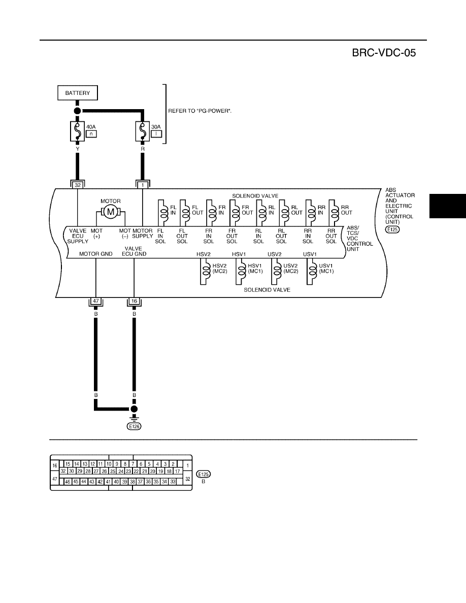
TROUBLE DIAGNOSIS
BRC-21
[VDC/TCS/ABS]
C
D
E
G
H
I
J
K
L
M
A
B
BRC
2005 Pathfinder
WFWA0135E
|
|
|
TROUBLE DIAGNOSIS BRC-21 [VDC/TCS/ABS] C D E G H I J K L M A B BRC
2005 Pathfinder WFWA0135E |