Nissan Pathfinder (2005 year). Manual - part 99
VEHICLE SECURITY (THEFT WARNING) SYSTEM
BL-79
C
D
E
F
G
H
J
K
L
M
A
B
BL
2005 Pathfinder
CONSULT-II INSPECTION PROCEDURE
CAUTION:
If CONSULT-II is used with no connection of CONSULT-II CONVERTER, malfunctions might be
detected in self-diagnosis depending on control unit which carries out CAN communication.
1.
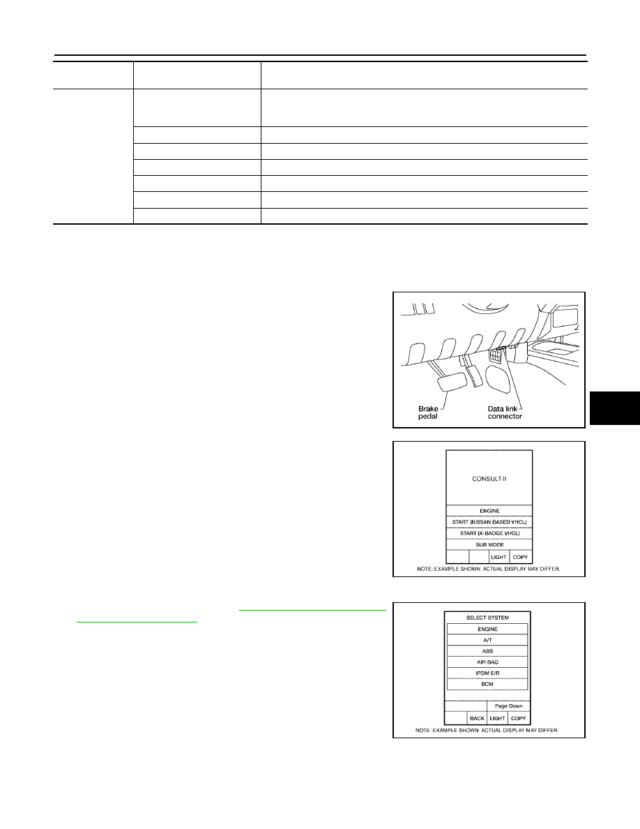
Turn ignition switch OFF.
2.
Connect CONSULT-II and CONSULT-II CONVERTER to the
data link connector.
3.
Turn ignition switch ON.
4.
Touch “START (NISSAN BASED VHCL)".
5.
Touch “BCM”.
If "BCM" is not indicated, refer to
.
BCM diagnostic
test item
Diagnostic mode
Description
Inspection by part
WORK SUPPORT
Supports inspections and adjustments. Commands are transmitted to the BCM
for setting the status suitable for required operation, input/output signals are
received from the BCM and received data is displayed.
DATA MONITOR
Displays BCM input/output data in real time.
ACTIVE TEST
Operation of electrical loads can be checked by sending drive signal to them.
SELF-DIAG RESULTS
Displays BCM self-diagnosis results.
CAN DIAG SUPPORT MNTR
The result of transmit/receive diagnosis of CAN communication can be read.
ECU PART NUMBER
BCM part number can be read.
CONFIGURATION
Performs BCM configuration read/write functions.
BBIA0538E
BCIA0029E
BCIA0030E