Nissan Pathfinder (2005 year). Manual - part 33


  Index      Manuals     Nissan Pathfinder (2005 year) - Service and Repair Manual


Search            copyright infringement  


Content      ..     31      32      33      34     ..


Nissan Pathfinder (2005 year). Manual - part 33


ON-VEHICLE SERVICE

AT-235

D

E

F

G

H

I

J

K

L

M

A

B

AT

2005 Pathfinder

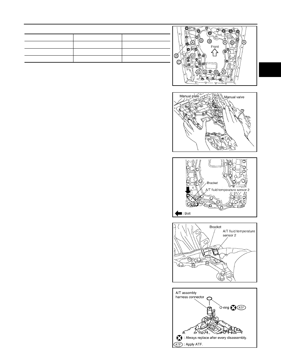
11. Remove bolts A, B and C from control valve with TCM.

12. Remove control valve with TCM from transmission case.

CAUTION:

When removing, be careful with the manual valve notch and
manual plate height. Remove it vertically.

13. Remove A/T fluid temperature sensor 2 with bracket from con-

trol valve with TCM.

14. Remove bracket from A/T fluid temperature sensor 2.

15. Remove O-ring from A/T assembly harness connector.

Bolt symbol

Length mm (in)

Number of bolts

A

42 (1.65)

5

B

55 (2.17)

6

C

40 (1.57)

1

SCIA5139E

SCIA5142E

SCIA5301E

SCIA5264E

SCIA5155E

AT-236

ON-VEHICLE SERVICE

2005 Pathfinder

16. Disconnect TCM connectors.

CAUTION:

Be careful not to damage connectors.

17. Remove A/T assembly harness connector from control valve

with TCM using suitable tool.

18. Disconnect TCM connector and park/neutral position switch

connector

CAUTION:

Be careful not to damage connectors.

SCIA5447E

SCIA5448E

SCIA5449E

ON-VEHICLE SERVICE

AT-237

D

E

F

G

H

I

J

K

L

M

A

B

AT

2005 Pathfinder

Installation

1.

Connect TCM connector and park/neutral position switch con-
nector.

2.

Install A/T assembly harness connector to control valve with
TCM.

3.

Connect TCM connector.

4.

Install new O-ring in A/T assembly harness connector.

CAUTION:

Do not reuse O-ring.

Apply ATF to O-ring.

SCIA5449E

SCIA5450E

SCIA5447E

SCIA5155E

AT-238

ON-VEHICLE SERVICE

2005 Pathfinder

5.

Install A/T fluid temperature sensor 2 to bracket.

6.

Install A/T fluid temperature sensor 2 (with bracket) in control
valve with TCM. Tighten A/T fluid temperature sensor 2 bolt to
the specified torque. Refer to

AT-233, "COMPONENTS"

.

CAUTION:

Adjust bolt hole of bracket to bolt hole of control valve with
TCM.

7.

Install control valve with TCM in transmission case.

CAUTION:

Make sure that turbine revolution sensor is securely
installed into turbine revolution sensor hole.

Hang down revolution sensor harness toward outside so
as not to disturb installation of control valve with TCM.

Adjust A/T assembly harness connector of control valve
with TCM to terminal hole of transmission case.

Assemble it so that manual valve cutout is engaged with
manual plate projection.

SCIA5264E

SCIA5301E

SCIA5034E

SCIA5142E

ON-VEHICLE SERVICE

AT-239

D

E

F

G

H

I

J

K

L

M

A

B

AT

2005 Pathfinder

8.

Install bolts A, B and C in control valve with TCM.

9.

Tighten bolt 1, 2 and 3 temporarily to prevent dislocation. After
that tighten them in order (1

2

3). Then tighten other bolts.

10. Tighten control valve with TCM bolts to the specified torque.

Refer to

AT-233, "COMPONENTS"

.

11. Connect A/T fluid temperature sensor 2 connector.

12. Securely fasten terminal cord assembly and A/T fluid tempera-

ture sensor 2 harness with terminal clips.

13. Connect revolution sensor connector.

14. Securely fasten revolution sensor harness with terminal clips.

15. Install oil pan to transmission case. Refer to

AT-231, "Installation"

.

Bolt symbol

Length mm (in)

Number of bolts

A

42 (1.65)

5

B

55 (2.17)

6

C

40 (1.57)

1

SCIA5139E

SCIA5140E

SCIA5446E

SCIA3969E

AT-240

ON-VEHICLE SERVICE

2005 Pathfinder

16. Pull up A/T assembly harness connector.

CAUTION:

Be careful not to damage connector.

17. Install snap ring to A/T assembly harness connector.

18. Connect A/T assembly harness connector.

19. Connect the negative battery terminal.

20. Refill the A/T with fluid and check for fluid leakage. Refer to

MA-

24, "Changing the Automatic Transmission Fluid (ATF)"

.

A/T FLUID TEMPERATURE SENSOR 2 REMOVAL AND INSTALLATION
Removal

1.

Disconnect negative battery terminal.

2.

Drain A/T fluid. Refer to

MA-24, "Changing the Automatic Transmission Fluid (ATF)"

.

3.

Remove oil pan and oil pan gasket. Refer to

AT-231, "Removal"

.

4.

Straighten terminal clip to free A/T fluid temperature sensor 2
harness.

5.

Disconnect A/T fluid temperature sensor 2 connector.

CAUTION:

Be careful not to damage connector.

6.

Remove A/T fluid temperature sensor 2 with bracket from con-
trol valve with TCM.

SCIA5038E

SCIA5039E

SCIA5146E

SCIA5253E

ON-VEHICLE SERVICE

AT-241

D

E

F

G

H

I

J

K

L

M

A

B

AT

2005 Pathfinder

7.

Remove bracket from A/T fluid temperature sensor 2.

Installation

1.

Install A/T fluid temperature sensor 2 to bracket.

2.

Install A/T fluid temperature sensor 2 (with bracket) in control
valve with TCM. Tighten A/T fluid temperature sensor 2 bolt to
the specified torque. Refer to

AT-233, "COMPONENTS"

.

CAUTION:

Adjust bolt hole of bracket to bolt hole of control valve with
TCM.

3.

Connect A/T fluid temperature sensor 2 connector.

4.

Securely fasten A/T temperature sensor 2 harness with terminal
clip.

5.

Install oil pan to transmission case. Refer to

AT-231, "Installation"

.

6.

Connect the negative battery terminal.

7.

Refill the A/T with fluid and check for fluid leakage. Refer to

MA-24, "Changing the Automatic Transmis-

sion Fluid (ATF)"

.

SCIA5264E

SCIA5264E

SCIA5253E

SCIA5146E

AT-242

ON-VEHICLE SERVICE

2005 Pathfinder

Rear Oil Seal

UCS0038D

REMOVAL AND INSTALLATION
Removal

1.

Remove rear propeller shaft. Refer to

PR-10, "Removal and

Installation"

.

2.

Remove transfer from transmission (4WD models). Refer to

TF-

145, "Removal and Installation"

(ATX14B) or

TF-275, "Removal

and Installation"

(TX15B).

3.

Remove rear oil seal using suitable tool.

CAUTION:

Be careful not to scratch rear extension assembly (2WD
models) or adapter case assembly (4WD models).

Installation

1.

Install new rear oil seal into the extension case (2WD models) or
adapter case (4WD models) until it is flush with component face,
using suitable tool or Tool.

CAUTION:

Apply ATF to rear oil seal.

Do not reuse rear oil seal.

2.

Install transfer to transmission (4WD models). Refer to

TF-145,

"Removal and Installation"

(ATX14B) or

TF-275, "Removal and

Installation"

(TX15B).

3.

Install rear propeller shaft. Refer to

PR-10, "Removal and Instal-

lation"

.

4.

Check the A/T fluid level and for fluid leakage. Refer to

MA-22,

"Checking the Automatic Transmission Fluid (ATF)"

.

SCIA5254E

Tool number

: ST33400001 (J-26082)

WCIA0475E


Content      ..     31      32      33      34     ..