Nissan Pathfinder (2005 year). Manual - part 25


  Index      Manuals     Nissan Pathfinder (2005 year) - Service and Repair Manual


Search            copyright infringement  


Content      ..     23      24      25      26     ..


Nissan Pathfinder (2005 year). Manual - part 25


DTC P1846 ATF PRESSURE SWITCH 6

AT-171

D

E

F

G

H

I

J

K

L

M

A

B

AT

2005 Pathfinder

Diagnostic Procedure

UCS003QM

1.

CHECK INPUT SIGNAL

With CONSULT-II

1.

Start the engine.

2.

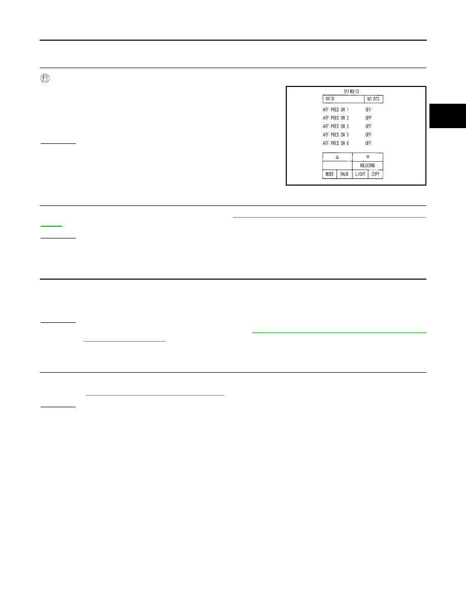
Select “ECU INPUT SIGNALS” or “MAIN SIGNALS” in “DATA
MONITOR” mode for “A/T” with CONSULT-II.

3.

Drive vehicle in the “D” position (2nd

Þ

3rd gear), and confirm

the ON/OFF actuation of the “ATF PRES SW 6”.

OK or NG

OK

>> GO TO 4.

NG

>> GO TO 2.

2.

CHECK TCM POWER SUPPLY AND GROUND CIRCUIT

Check TCM power supply and ground circuit. Refer to

AT-172, "MAIN POWER SUPPLY AND GROUND CIR-

CUIT"

.

OK or NG

OK

>> GO TO 3.

NG

>> Repair or replace damaged parts.

3.

DETECT MALFUNCTIONING ITEM

Check the following.

The A/T assembly harness connector pin terminals for damage or loose connection with harness connec-
tor.

OK or NG

OK

>> Replace the control valve with TCM. Refer to

AT-233, "Control Valve With TCM and A/T Fluid

Temperature Sensor 2"

.

NG

>> Repair or replace damaged parts.

4.

CHECK DTC

Perform “DTC Confirmation Procedure”.

Refer to

AT-170, "DTC Confirmation Procedure"

.

OK or NG

OK

>> INSPECTION END

NG

>> GO TO 2.

PCIA0067E

AT-172

MAIN POWER SUPPLY AND GROUND CIRCUIT

2005 Pathfinder

MAIN POWER SUPPLY AND GROUND CIRCUIT

PFP:00100

Wiring Diagram — AT — MAIN

UCS003QN

BCWA0386E

MAIN POWER SUPPLY AND GROUND CIRCUIT

AT-173

D

E

F

G

H

I

J

K

L

M

A

B

AT

2005 Pathfinder

TCM terminals and data are reference value. Measured between each terminal and ground.

Diagnostic Procedure

UCS003QO

1.

CHECK TCM POWER SOURCE STEP 1

1.

Turn ignition switch OFF.

2.

Disconnect A/T assembly harness connector.

3.

Check voltage between A/T assembly harness connector termi-
nals and ground.

OK or NG

OK

>> GO TO 2.

NG

>> GO TO 3.

2.

CHECK TCM POWER SOURCE STEP 2

1.

Disconnect A/T assembly harness connector.

2.

Turn ignition switch ON. (Do not start engine.)

3.

Check voltage between A/T assembly harness connector termi-
nals and ground.

OK or NG

OK

>> GO TO 4.

NG

>> GO TO 3.

Terminal

Wire

color

Item

Condition

Data (Approx.)

1

R/B

Power supply
(Memory back-up)

Always

Battery voltage

2

R/B

Power supply
(Memory back-up)

Always

Battery voltage

5

B

Ground

Always

0V

6

W/G

Power supply

Battery voltage

0V

10

B

Ground

Always

0V

Item

Connector

Terminal

Voltage

TCM

F9

1 - Ground

Battery voltage

2 - Ground

6 - Ground

0V

SCIA2104E

Item

Connector

Terminal

Voltage

TCM

F9

1 - Ground

Battery voltage

2 - Ground

6 - Ground

SCIA2105E

AT-174

MAIN POWER SUPPLY AND GROUND CIRCUIT

2005 Pathfinder

3.

DETECT MALFUNCTIONING ITEM

Check the following.

Harness for short or open between battery and A/T assembly harness connector terminals 1, 2

Harness for short or open between ignition switch and A/T assembly harness connector terminal 6

10A fuse (No. 22, located in the fuse and fusible link block) and 10A fuse (No. 49, located in the IPDM E/
R)

Ignition switch. Refer to

PG-4, "POWER SUPPLY ROUTING CIRCUIT"

.

OK or NG

OK

>> GO TO 4.

NG

>> Repair or replace damaged parts.

4.

CHECK TCM GROUND CIRCUIT

1.

Turn ignition switch OFF.

2.

Disconnect A/T assembly harness connector.

3.

Check continuity between A/T assembly harness connector ter-
minals and ground.

If OK, check harness for short to ground and short to power.

OK or NG

OK

>> GO TO 5.

NG

>> Repair open circuit or short to ground or short to power

in harness or connectors.

5.

DETECT MALFUNCTIONING ITEM

Check the following.

The A/T assembly harness connector terminals for damage or loose connection with harness connector.

OK or NG

OK

>> GO TO 6.

NG

>> Repair or replace damaged parts.

6.

PERFORM SELF-DIAGNOSIS

Perform self-diagnosis. Refer to

AT-87, "SELF-DIAGNOSTIC RESULT MODE"

.

OK or NG

OK

>> INSPECTION END

NG-1

>> Self-diagnosis does not activate: GO TO 7.

NG-2

>> DTC is displayed: Check the malfunctioning system. Refer to

AT-87, "SELF-DIAGNOSTIC

RESULT MODE"

.

Item

Connector

Terminal

Continuity

TCM

F9

5, 10 - Ground

Yes

SCIA2106E

MAIN POWER SUPPLY AND GROUND CIRCUIT

AT-175

D

E

F

G

H

I

J

K

L

M

A

B

AT

2005 Pathfinder

7.

CHECK TERMINAL CORD ASSEMBLY

1.

Remove control valve with TCM. Refer to

AT-233, "Control Valve With TCM and A/T Fluid Temperature

Sensor 2"

.

2.

Disconnect A/T assembly harness connector and TCM connector.

3.

Check continuity between A/T assembly harness connector ter-
minals and TCM connector terminals.

4.

Check continuity between A/T assembly harness connector ter-
minals and TCM connector terminals.

5.

If OK, check harness for short to ground and short to power.

OK or NG

OK

>> Replace the control valve with TCM. Refer to

AT-233, "Control Valve With TCM and A/T Fluid

Temperature Sensor 2"

.

NG

>> Replace open circuit or short to ground and short to power in harness or connectors.

Item

Connector

Terminal

Voltage

A/T assembly harness connector

F9

1

Yes

TCM connector

F502

9

A/T assembly harness connector

F9

2

Yes

TCM connector

F502

10

A/T assembly harness connector

F9

6

Yes

TCM connector

F502

4

SCIA5464E

Item

Connector

Terminal

Voltage

A/T assembly harness connector

F9

5

Yes

TCM connector

F504

21

A/T assembly harness connector

F9

10

Yes

TCM connector

F504

22

SCIA5465E

AT-176

CLOSED THROTTLE POSITION AND WIDE OPEN THROTTLE POSITION CIR-

CUIT

2005 Pathfinder

CLOSED THROTTLE POSITION AND WIDE OPEN THROTTLE POSITION CIR-
CUIT

PFP:18002

CONSULT-II Reference Value

UCS0037C

Diagnostic Procedure

UCS0037D

1.

CHECK CAN COMMUNICATION LINE

Perform the self-diagnosis. Refer to

AT-87, "SELF-DIAGNOSTIC RESULT MODE"

.

Is a malfunction in the CAN communication indicated in the results?

YES

>> Check CAN communication line. Refer to

AT-100, "DTC U1000 CAN COMMUNICATION LINE"

.

NO

>> GO TO 2.

2.

CHECK THROTTLE POSITION SIGNAL CIRCUIT

With CONSULT-II

1.

Turn ignition switch “ON”. (Do not start engine.)

2.

Select “ECU INPUT SIGNALS” in “DATA MONITOR” mode for
“A/T” with CONSULT-II.

3.

Depress accelerator pedal and read out the value of “CLSD THL
POS” and “W/O THL POS”.

OK or NG

OK

>> INSPECTION END

NG

>> Check the following. If NG, repair or replace damaged

parts.

Perform the self-diagnosis for “ENGINE” with CON-
SULT-II.

Open circuit or short to ground or short to power in harness or connectors.

Pin terminals for damage or loose connection with harness connector.

Item name

Condition

Display value

CLSD THL POS

Released accelerator pedal.

ON

Fully depressed accelerator pedal.

OFF

W/O THL POS

Fully depressed accelerator pedal.

ON

Released accelerator pedal.

OFF

PCIA0070E

BRAKE SIGNAL CIRCUIT

AT-177

D

E

F

G

H

I

J

K

L

M

A

B

AT

2005 Pathfinder

BRAKE SIGNAL CIRCUIT

PFP:25320

CONSULT-II Reference Value

UCS0037E

Diagnostic Procedure

UCS0037F

1.

CHECK CAN COMMUNICATION LINE

Perform the self-diagnosis. Refer to

AT-87, "SELF-DIAGNOSTIC RESULT MODE"

.

Is a malfunction in the CAN communication indicated in the results?

YES

>> Check CAN communication line. Refer to

AT-100, "DTC U1000 CAN COMMUNICATION LINE"

.

NO

>> GO TO 2.

2.

CHECK STOP LAMP SWITCH CIRCUIT

With CONSULT-II

1.

Turn ignition switch “ON”. (Do not start engine.)

2.

Select “ECU INPUT SIGNALS” in “DATA MONITOR” mode for
“A/T” with CONSULT-II.

3.

Read out ON/OFF switching action of the “BRAKE SW”.

OK or NG

OK

>> INSPECTION END

NG

>> GO TO 3.

3.

CHECK STOP LAMP SWITCH

Check continuity between stop lamp switch harness connector termi-
nals 1 and 2.

Check stop lamp switch after adjusting brake pedal — refer to

BR-6, "BRAKE PEDAL"

.

OK or NG

OK

>> INSPECTION END

NG

>> Check the following. If NG, repair or replace damaged parts.

Harness for short or open between battery and stop lamp switch.

Harness for short or open between stop lamp switch and combination meter.

Item name

Condition

Display value

BRAKE SW

Depressed brake pedal.

ON

Released brake pedal.

OFF

PCIA0070E

Item

Connector

Condition

Terminal

Continuity

Stop lamp

switch har-

ness con-

nector

E38

When brake pedal is
depressed

1 - 2

Yes

When brake pedal is
released

No

SCIA2144E

AT-178

OVERDRIVE CONTROL SWITCH

2005 Pathfinder

OVERDRIVE CONTROL SWITCH

PFP:25130

CONSULT-II Reference Value

UCS0040Q

Diagnostic Procedure

UCS0040P

1.

CHECK CAN COMMUNICATION LINE

Perform the self-diagnosis. Refer to

AT-87, "SELF-DIAGNOSTIC RESULT MODE"

.

Is any malfunction in the CAN communication indicated in the results?

YES

>> Check CAN communication line. Refer to

AT-100, "DTC U1000 CAN COMMUNICATION LINE"

.

NO

>> GO TO 2.

2.

CHECK OVERDRIVE CONTOROL SWITCH CIRCUIT

With CONSULT-II

1.

Turn ignition switch “ON”.

2.

Select “ECU INPUT SIGNALS” in “DATA MONITOR” mode for
“A/T” with CONSULT-II.

3.

Read out “OD CONT SW”.
Check the signal of the overdrive control switch is indicated
properly.

Without CONSULT-II

1.

Turn ignition switch “ON”. (Do not start engine)

2.

Check voltage between A/T control device connector terminal and ground.

OK or NG

OK

>> GO TO 5.

NG

>> GO TO 3.

Item name

Condition

Display value

OD CONT SW

Releasing overdrive control switch

OFF

Holding overdrive control switch

ON

Monitor item

Condition

Display value

OD CONT SW

Releasing overdrive control switch

OFF

Holding overdrive control switch

ON

LCIA0339E

Item

Connector

No.

Terminal No.

Condition

Data

(Approx.)

Overdrive

control switch

M156

7 - Ground

Releasing overdrive
control switch

Battery
voltage

Holding overdrive
control switch

0V


Content      ..     23      24      25      26     ..