Nissan Pathfinder (2005 year). Manual - part 21
DTC P1730 A/T INTERLOCK
AT-139
D
E
F
G
H
I
J
K
L
M
A
B
AT
2005 Pathfinder
DTC P1730 A/T INTERLOCK
PFP:00000
Description
UCS0034O
●
Fail-safe function to detect interlock conditions.
On Board Diagnosis Logic
UCS0034P
●
This is an OBD-II self-diagnostic item.
●
Diagnostic trouble code “P1730 A/T INTERLOCK” with CONSULT-II or 12th judgement flicker without
CONSULT-II is detected when TCM does not receive the proper voltage signal from the sensor and
switch.
●
TCM monitors and compares gear position and conditions of each ATF pressure switch when gear is
steady.
Possible Cause
UCS0034Q
●
Harness or connectors
(The solenoid and switch circuit is open or shorted.)
●
Low coast brake solenoid valve
●
ATF pressure switch 2
DTC Confirmation Procedure
UCS0034R
NOTE:
If “DTC Confirmation Procedure” has been previously performed, always turn ignition switch “OFF”
and wait at least 10 seconds before performing the next test.
After the repair, perform the following procedure to confirm the malfunction is eliminated.
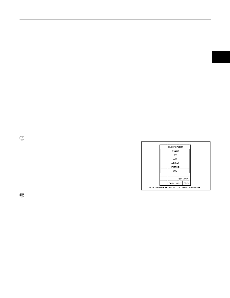
WITH CONSULT-II
1.
Turn ignition switch “ON”. (Do not start engine.)
2.
Select “DATA MONITOR” mode for “A/T” with CONSULT-II.
3.
Start engine.
4.
Drive vehicle and maintain the following conditions for at least 2
consecutive seconds.
Selector lever: “D” position
5.
If DTC is detected, go to
AT-140, "Diagnostic Procedure"
.
WITH GST
Follow the procedure “WITH CONSULT-II”.
BCIA0030E