Nissan Pathfinder (2005 year). Manual - part 17
DTC P0700 TCM
AT-107
D
E
F
G
H
I
J
K
L
M
A
B
AT
2005 Pathfinder
DTC P0700 TCM
PFP:31036
Description
UCS0032K
The TCM consists of a microcomputer and connectors for signal input and output and for power supply. The
TCM controls the A/T.
On Board Diagnosis Logic
UCS0032L
●
This is an OBD-II self-diagnostic item.
●
Diagnostic trouble code “P0700 TCM” with CONSULT-II is detected when the TCM is malfunctioning.
Possible Cause
UCS0032M
TCM.
DTC Confirmation Procedure
UCS0032N
NOTE:
If “DTC Confirmation Procedure” has been previously performed, always turn ignition switch “OFF”
and wait at least 10 seconds before performing the next test.
After the repair, perform the following procedure to confirm the malfunction is eliminated.
WITH CONSULT-II
1.
Turn ignition switch “ON”. (Do not start engine.)
2.
Select “DATA MONITOR” mode for “A/T” with CONSULT-II.
3.
Start engine.
4.
Run engine for at least 2 consecutive seconds at idle speed.
5.
If DTC is detected, go to
AT-107, "Diagnostic Procedure"
.
WITH GST
Follow the procedure “WITH CONSULT-II”.
Diagnostic Procedure
UCS0032O
1.
CHECK DTC
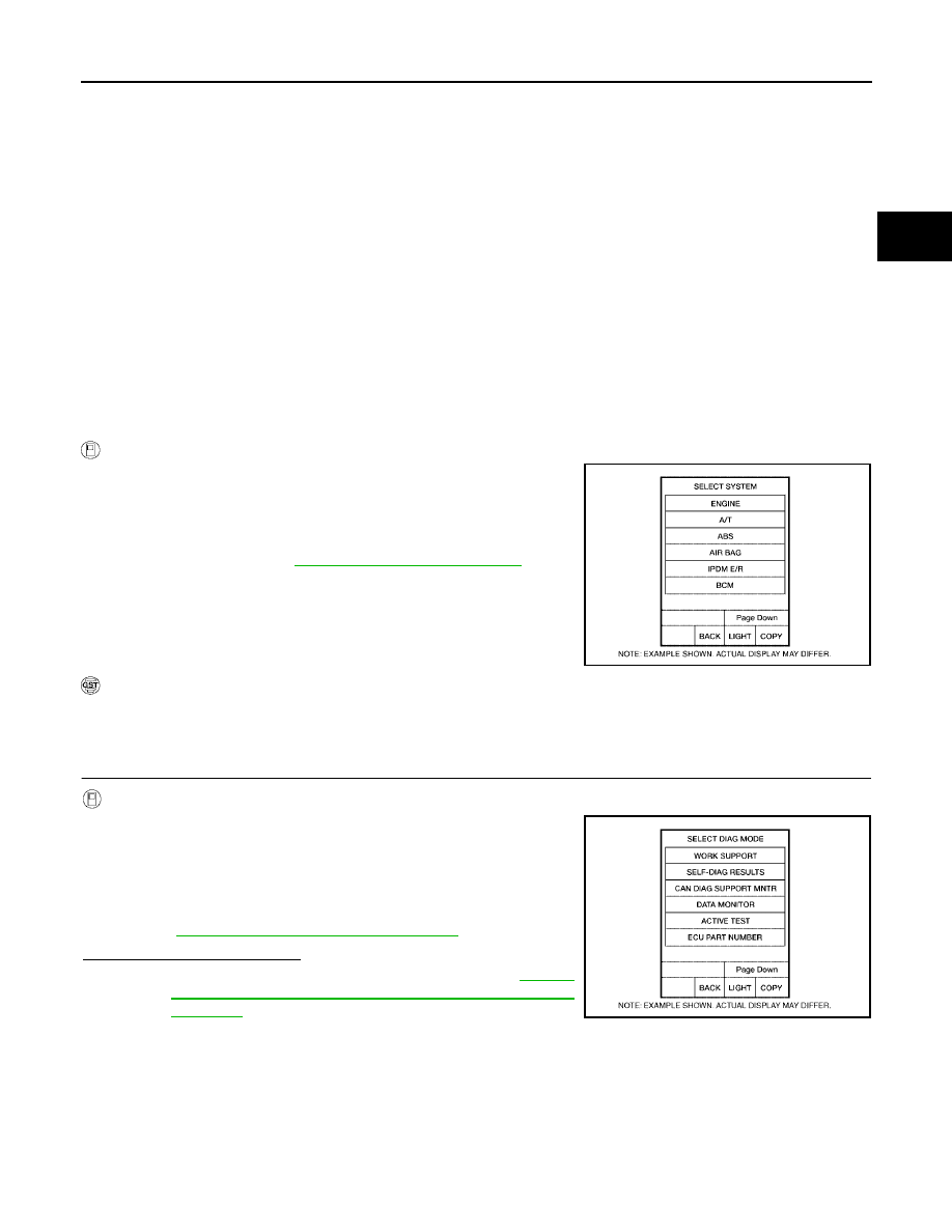
With CONSULT-II
1.
Turn ignition switch “ON”. (Do not start engine.)
2.
Select “SELF DIAG RESULTS” mode for “A/T” with CONSULT-
II.
3.
Touch “ERASE”.
4.
Turn ignition switch “OFF” and wait at least 10 seconds.
5.
Perform
AT-107, "DTC Confirmation Procedure"
.
Is the “TCM” displayed again?
YES
>> Replace the control valve with TCM. Refer to
"Control Valve With TCM and A/T Fluid Temperature
Sensor 2"
.
NO
>> INSPECTION END
BCIA0030E
BCIA0031E