Nissan Pathfinder (2005 year). Manual - part 16


  Index      Manuals     Nissan Pathfinder (2005 year) - Service and Repair Manual


Search            copyright infringement  


Content      ..     14      15      16      17     ..


Nissan Pathfinder (2005 year). Manual - part 16


TROUBLE DIAGNOSIS

AT-99

D

E

F

G

H

I

J

K

L

M

A

B

AT

2005 Pathfinder

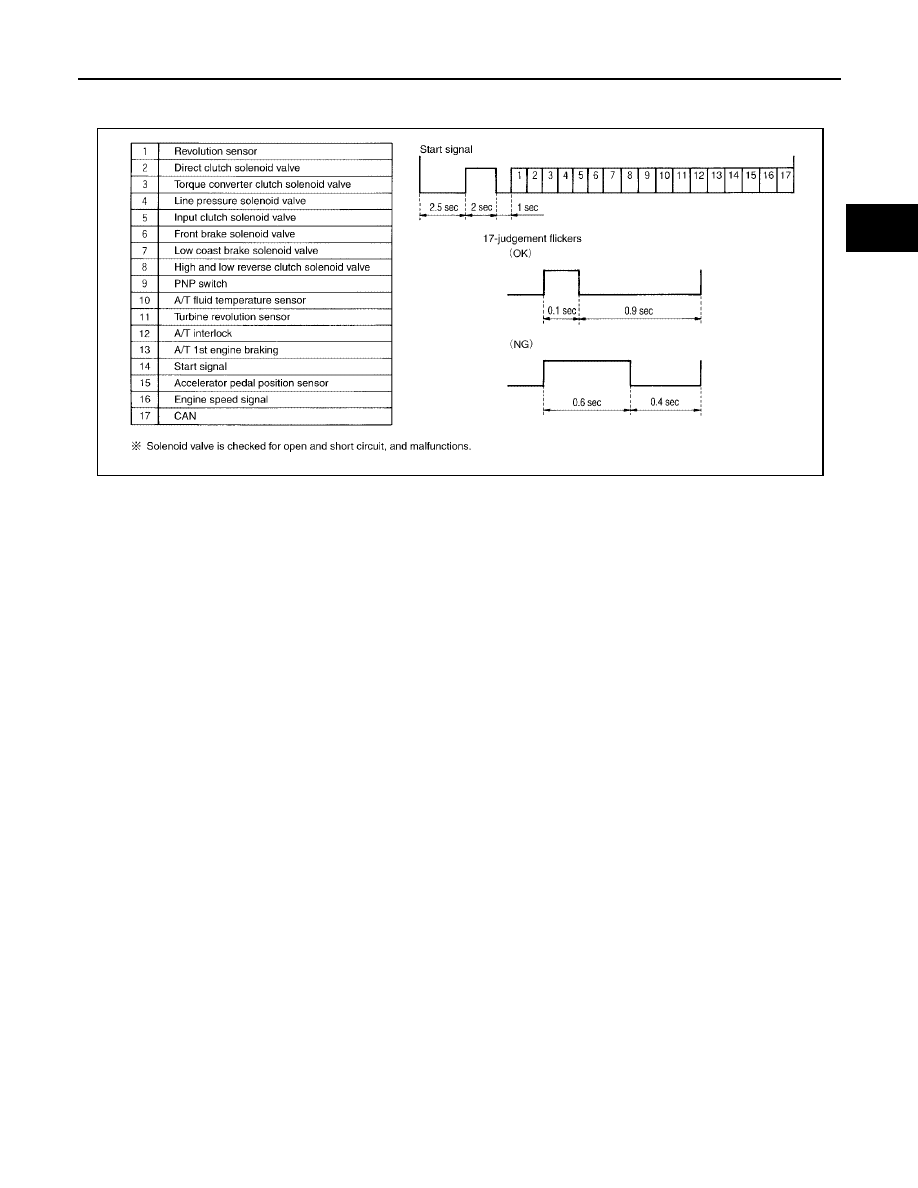
Judgement Self-diagnosis Code

If there is a malfunction, the lamp lights up for the time corresponding to the suspect circuit.

Erase Self-diagnosis

In order to make it easier to find the cause of hard-to-duplicate malfunctions, malfunction information is
stored into the control unit as necessary during use by the user. This memory is not erased no matter how
many times the ignition switch is turned ON and OFF.

However, this information is erased by turning ignition switch OFF after executing self-diagnostics or by
erasing the memory using the CONSULT-II.

SCIA4758E

AT-100

DTC U1000 CAN COMMUNICATION LINE

2005 Pathfinder

DTC U1000 CAN COMMUNICATION LINE

PFP:23710

Description

UCS00329

CAN (Controller Area Network) is a serial communication line for real time application. It is an on-vehicle mul-
tiplex communication line with high data communication speed and excellent malfunction detection ability.
Many electronic control units are equipped onto a vehicle, and each control unit shares information and links
with other control units during operation (not independent). In CAN communication, control units are con-
nected with 2 communication lines (CAN H line, CAN L line) allowing a high rate of information transmission
with less wiring. Each control unit transmits/receives data but selectively reads required data only.

On Board Diagnosis Logic

UCS0032A

This is an OBD-II self-diagnostic item.

Diagnostic trouble code “U1000 CAN COMM CIRCUIT” with CONSULT-II or 17th judgement flicker with-
out CONSULT-II is detected when TCM cannot communicate to other control units.

Possible Cause

UCS0032B

Harness or connectors
(CAN communication line is open or shorted.)

DTC Confirmation Procedure

UCS0032C

NOTE:
If “DTC Confirmation Procedure” has been previously performed, always turn ignition switch “OFF”
and wait at least 10 seconds before performing the next test.
After the repair, perform the following procedure to confirm the malfunction is eliminated.

WITH CONSULT-II

1.

Turn ignition switch “ON”. (Do not start engine.)

2.

Select “DATA MONITOR” mode for “ENGINE” with CONSULT-II.

3.

Start engine and wait for at least 6 seconds.

4.

If DTC is detected, go to

AT-102, "Diagnostic Procedure"

.

WITH GST

Follow the procedure “WITH CONSULT-II”.

BCIA0030E

DTC U1000 CAN COMMUNICATION LINE

AT-101

D

E

F

G

H

I

J

K

L

M

A

B

AT

2005 Pathfinder

Wiring Diagram — AT — CAN

UCS003PQ

BCWA0320E

AT-102

DTC U1000 CAN COMMUNICATION LINE

2005 Pathfinder

TCM terminal and Data are reference value.

Diagnostic Procedure

UCS0032D

1.

CHECK CAN COMMUNICATION CIRCUIT

With CONSULT-II

1.

Turn ignition switch “ON” and start engine.

2.

Select “SELF-DIAG RESULTS” mode for “A/T” with CONSULT-
II.

Is any malfunction of the “CAN COMM CIRCUIT” indicated?

YES

>> Print out CONSULT-II screen, GO TO LAN section.

Refer to

LAN-4, "Precautions When Using CONSULT-II"

.

NO

>> INSPECTION END

Terminal

No.

Wire

color

Item

Condition

Data (Approx.)

3

L

CAN H

8

P

CAN L

PCIA0061E

DTC P0615 START SIGNAL CIRCUIT

AT-103

D

E

F

G

H

I

J

K

L

M

A

B

AT

2005 Pathfinder

DTC P0615 START SIGNAL CIRCUIT

PFP:25230

Description

UCS0032E

TCM prohibits cranking other than at “P” or “N” position.

CONSULT-II Reference Value

UCS0032F

On Board Diagnosis Logic

UCS0032G

This is not an OBD-II self-diagnostic item.

Diagnostic trouble code “P0615 STARTER RELAY/CIRC” with CONSULT-II or 14th judgement flicker
without CONSULT-II is detected when park/neutral (PNP) relay (starter relay) is switched “ON” other than
at “P” or “N” position. (Or when switched “OFF” at “P” or “N” position).

Possible Cause

UCS0032H

Harness or connectors
[The park/neutral position (PNP) relay (starter relay) and TCM circuit is open or shorted.]

Park/neutral position (PNP) relay (starter relay)

DTC Confirmation Procedure

UCS0032I

NOTE:
If “DTC Confirmation Procedure” has been previously performed, always turn ignition switch “OFF”
and wait at least 10 seconds before performing the next test.
After the repair, perform the following procedure to confirm the malfunction is eliminated.

WITH CONSULT-II

1.

Turn ignition switch “ON”. (Do not start engine.)

2.

Select “DATA MONITOR” mode for “A/T” with CONSULT-II.

3.

Start engine.

4.

Drive vehicle for at least 2 consecutive seconds.

5.

If DTC is detected, go to

AT-105, "Diagnostic Procedure"

.

Item name

Condition

Display value

STARTER RELAY

Selector lever in “N”, “P” positions.

ON

Selector lever in other position.

OFF

BCIA0030E

AT-104

DTC P0615 START SIGNAL CIRCUIT

2005 Pathfinder

Wiring Diagram — AT — STSIG

UCS003PR

BCWA0385E

DTC P0615 START SIGNAL CIRCUIT

AT-105

D

E

F

G

H

I

J

K

L

M

A

B

AT

2005 Pathfinder

TCM terminals and data are reference value. Measured between each terminal and ground.

Diagnostic Procedure

UCS003PS

1.

CHECK STARTER RELAY

With CONSULT-II

1.

Turn ignition switch ON. (Do not start engine.)

2.

Select “SELECTION FROM MENU” in “DATA MONITOR” mode
for “A/T” with CONSULT-II and check monitor “STARTER
RELAY” ON/OFF.

Without CONSULT-II

1.

Turn ignition switch ON. (Do not start engine.)

2.

Check voltage between the IPDM E/R connector and ground.

OK or NG

OK

>> GO TO 5.

NG

>> GO TO 2.

2.

CHECK HARNESS BETWEEN A/T ASSEMBLY HARNESS CONNECTOR AND IPDM E/R CONNEC-

TOR

1.

Turn ignition switch OFF.

2.

Disconnect A/T assembly harness connector and IPDM E/R connector.

3.

Check continuity between A/T assembly harness connector and
IPDM E/R connector.

4.

If OK, check harness for short to ground and short to power.

5.

Reinstall any part removed.

OK or NG

OK

>> GO TO 3.

NG

>> Repair open circuit or short to ground or short to power in harness or connectors.

Terminal

Wire

color

Item

Condition

Data (Approx.)

9

R

Starter relay

Selector lever in “N”, “ P” positions.

Battery voltage

Selector lever in other positions.

0V

PCIA0056E

Item

Connector

Terminal

Shift position

Voltage

(Approx.)

Starter relay

E122

48

Ground

“N” and “P”

Battery voltage

“R” and “D”

0V

LCIA0320E

Item

Connector

Terminal

Continuity

A/T assembly harness
connector

F9

9

Yes

IPDM E/R connector

E122

48

SCIA6254E

AT-106

DTC P0615 START SIGNAL CIRCUIT

2005 Pathfinder

3.

CHECK TERMINAL CORD ASSEMBLY

1.

Remove control valve with TCM. Refer to

AT-233, "Control Valve With TCM and A/T Fluid Temperature

Sensor 2"

.

2.

Disconnect A/T assembly harness connector and TCM connector.

3.

Check continuity between A/T assembly harness connector ter-
minal and TCM connector terminal.

4.

If OK, check harness for short to ground and short to power.

5.

Reinstall any part removed.

OK or NG

OK

>> GO TO 4.

NG

>> Replace open circuit or short to ground and short to power in harness or connectors.

4.

DETECT MALFUNCTIONING ITEM

Check the following.

Starter relay, Refer to

SC-10, "STARTING SYSTEM"

.

IPDM E/R, Refer to

PG-17, "IPDM E/R (INTELLIGENT POWER DISTRIBUTION MODULE ENGINE

ROOM)"

.

OK or NG

OK

>> Replace the control valve with TCM. Refer to

AT-233, "Control Valve With TCM and A/T Fluid

Temperature Sensor 2"

.

NG

>> Repair or replace damaged parts.

5.

CHECK DTC

Perform

AT-103, "DTC Confirmation Procedure"

.

OK or NG

OK

>> INSPECTION END

NG

>> GO TO 2.

Item

Connector

Terminal

Continuity

A/T assembly harness
connector

F9

9

Yes

TCM connector

F502

8

SCIA5440E


Content      ..     14      15      16      17     ..