Nissan Teana J32. Manual - part 818


  Index      Nissan     Nissan Teana J32 (2008 year) - Service and Repair Manual


Search            


Content   ..  816  817  818  819   ..


Nissan Teana J32. Manual - part 818


MWI

METER SYSTEM

MWI-15

< FUNCTION DIAGNOSIS >

C

D

E

F

G

H

I

J

K

L

M

B

A

O

P

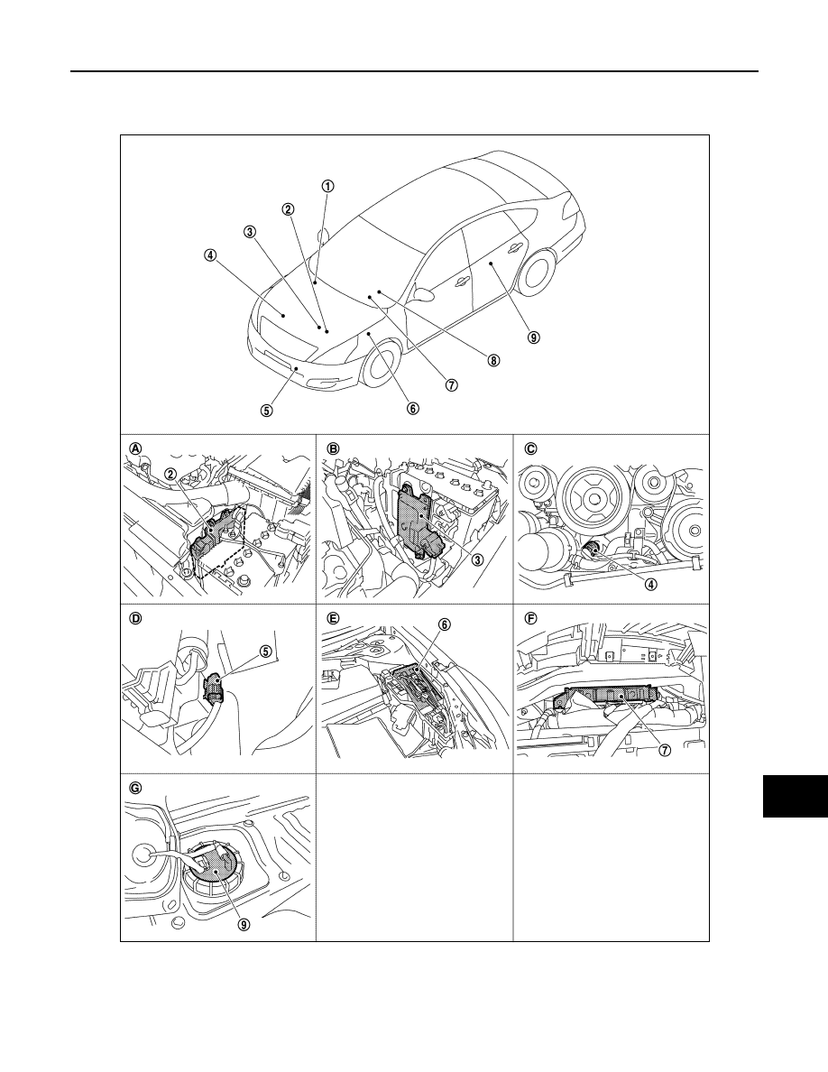
ENGINE COOLANT TEMPERATURE GAUGE : Component Parts Location

INFOID:0000000003879301

1.

ABS actuator and electric unit (con-
trol unit)

2.

ECM

3.

TCM

4.

Oil pressure switch

5.

Ambient sensor

6.

IPDM E/R

7.

BCM

8.

Combination meter

9.

Fuel level sensor unit and fuel pump

JPNIA1025ZZ

MWI-16

< FUNCTION DIAGNOSIS >

METER SYSTEM

ENGINE COOLANT TEMPERATURE GAUGE : Component Description

INFOID:0000000003792522

FUEL GAUGE

FUEL GAUGE : System Diagram

INFOID:0000000003792523

FUEL GAUGE : System Description

INFOID:0000000003792524

CONTROL OUTLINE

The combination meter reads the fuel level sensor signal from the fuel level sensor unit and indicates the fuel
level to the fuel gauge. 

REFUEL CONTROL

The combination meter accelerates the fuel gauge segment if the all conditions listed below are met, or the
ignition switch is ON from OFF.
• Ignition switch is ON position.
• The vehicle is not moving.
• The fuel level change by 15   (3 - 1/4 lmp gal) or more.

A.

Engine room (LH)

B.

Engine room (LH)

C.

Engine front side

D.

Front bumper (left back)

E.

Engine room (LH)

F.

Behind the combination meter

G.

Lower left side of rear seat

Unit

Description

Combination meter

Indicates the engine coolant temperature to the water temperature gauge according to the engine 
coolant temperature signal received from ECM via CAN communication. 

ECM

Transmits the engine coolant temperature signal to the combination meter via CAN communication. 

JPNIA0983GB

MWI

METER SYSTEM

MWI-17

< FUNCTION DIAGNOSIS >

C

D

E

F

G

H

I

J

K

L

M

B

A

O

P

FUEL GAUGE : Component Parts Location

INFOID:0000000003879302

1.

ABS actuator and electric unit (con-
trol unit)

2.

ECM

3.

TCM

4.

Oil pressure switch

5.

Ambient sensor

6.

IPDM E/R

7.

BCM

8.

Combination meter

9.

Fuel level sensor unit and fuel pump

A.

Engine room (LH)

B.

Engine room (LH)

C.

Engine front side

JPNIA1025ZZ

MWI-18

< FUNCTION DIAGNOSIS >

METER SYSTEM

FUEL GAUGE : Component Description

INFOID:0000000003792526

ODO/TRIP METER

ODO/TRIP METER : System Diagram

INFOID:0000000003792527

ODO/TRIP METER : System Description

INFOID:0000000003792528

• The ABS actuator and electric unit (control unit) reads the rectangular wave signal provided by the wheel

sensor and transmits the vehicle speed signal to the combination meter via CAN communication. 

• The combination meter converts the vehicle speed signal received via CAN communication to mileage, and

it displays the accumulated mileage to the odo/trip meter. 

D.

Front bumper (left back)

E.

Engine room (LH)

F.

Behind the combination meter

G.

Lower left side of rear seat

Unit

Description

Combination meter

Indicates the fuel gauge according to the fuel level sensor signal received from the fuel level sensor 
unit. 

Fuel level sensor unit

Refer to 

MWI-45, "Description"

.

JPNIA1015GB


Content   ..  816  817  818  819   ..