Nissan Teana J32. Manual - part 621
FRONT COIL SPRING AND STRUT
FSU-9
< ON-VEHICLE REPAIR >
C
D
F
G
H
I
J
K
L
M
A
B
FSU
N
O
P
ON-VEHICLE REPAIR
FRONT COIL SPRING AND STRUT
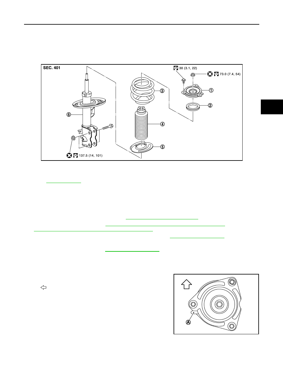
Exploded View
INFOID:0000000003811116
Removal and Installation
INFOID:0000000003811117
REMOVAL
1.
Remove tires.
2.
Remove lock plate of brake hose. Refer to
BR-19, "FRONT : Exploded View"
3.
Remove wheel sensor. Refer to
BRC-57, "FRONT WHEEL SENSOR : Exploded View"
BRC-151, "FRONT WHEEL SENSOR : Exploded View"
4.
Remove stabilizer connecting rod from strut assembly. Refer to
.
5.
Remove strut assembly from steering knuckle.
6.
Remove cowl top cover. Refer to
7.
Remove mounting bolts of strut mounting insulator, and then remove strut assembly.
INSTALLATION
Note the following, and install in the reverse order of removal.
• Become it in projection (A) an illustration to the vehicle outside.
• Perform final tightening of bolts and nuts, under unladen conditions
with tires on level ground.
1.
Strut mounting insulator
2.
Strut mounting bearing
3.
Coil spring
4.
Bound bumper
5.
Lower rubber seat
6.
Strut
Refer to
JPEIA0112GB
: Vehicle front
JPEIA0094ZZ