Nissan Teana J32. Manual - part 618


  Index      Nissan     Nissan Teana J32 (2008 year) - Service and Repair Manual


Search            


Content   ..  616  617  618  619   ..


Nissan Teana J32. Manual - part 618


FL-8

< ON-VEHICLE REPAIR >

FUEL LEVEL SENSOR UNIT, FUEL FILTER AND FUEL PUMP ASSEMBLY

INSTALLATION

Note to the following, and install in the reverse order of removal.

Fuel Level Sensor Unit

1.

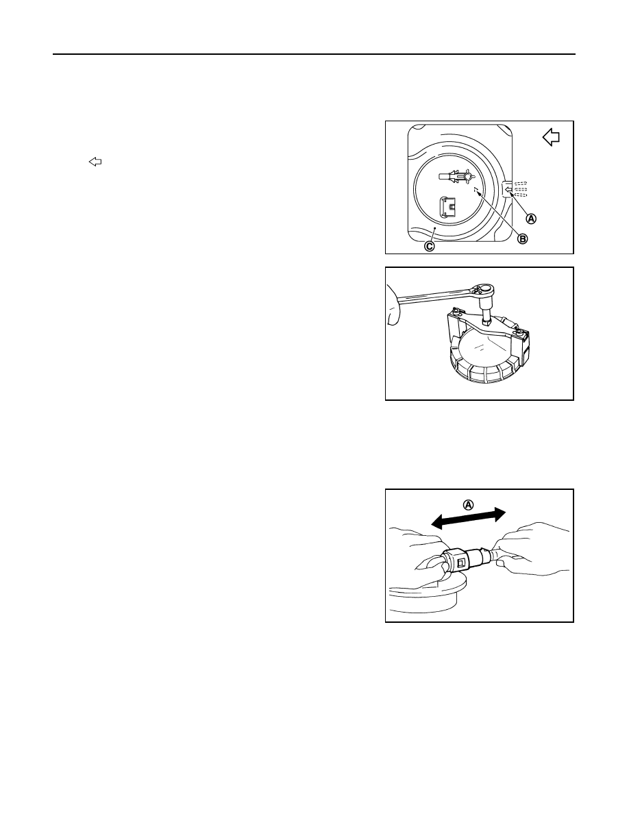
Install new seal packing to fuel tank without any twist.

2.

Align (B) with (A) as shown in the figure. Install fuel level sensor
unit, fuel filter and fuel pump assembly to fuel tank (C).

CAUTION:

• Never allow seal packing to drop.
• Never bend float arm during installing.

3.

Install seal packing for fuel level sensor unit, fuel filter and fuel
pump assembly with lock ring wrench (commercial service tool)
by turning clockwise.

CAUTION:

Install lock ring horizontally.

Quick Connector

Connect quick connector as follows:

1.

Check the connection for damage or any foreign materials.

2.

Align the connector with the tube, then insert the connector straight into the tube until a click sound is
heard.

3.

After connecting, check that the connection is secure by following method.
• Pull the tube and the connector to check they are securely

connected.

• Visually confirm that the two retainer tabs are connected to the

connector.

Inspection

INFOID:0000000003793253

INSPECTION AFTER INSTALLATION

Use the following procedure to check for fuel leakage.

1.

Turn ignition switch “ON” (with engine stopped), then check connections for leakage by applying fuel pres-
sure to fuel piping.

2.

Start engine and let it idle and check there are no fuel leakage at the fuel system connections.

: Vehicle front

PBIC4584J

PBIC0240E

A

:  Pull

JPBIA0140ZZ

FUEL TANK

FL-9

< ON-VEHICLE REPAIR >

C

D

E

F

G

H

I

J

K

L

M

A

FL

N

P

O

FUEL TANK

Exploded View

INFOID:0000000003793254

• In regard to the notation of torque in the figure, (A) shows an ISO standard, (B) shows a conventional stan-

dard.

Removal and Installation

INFOID:0000000003793255

WARNING:

Be sure to read “General Precautions” when working on the fuel system. Refer to 

FL-2, "General Pre-

cautions"

.

REMOVAL

• Drain fuel from fuel tank if necessary. Refer to 

FL-5, "Removal and Installation"

.

• Perform work on level place.
1.

Perform steps 2 to 7 of “REMOVAL” in “FUEL LEVEL SENSOR UNIT, FUEL FILTER AND FUEL PUMP
ASSEMBLY” on fuel level sensor units. Refer to 

FL-5, "Removal and Installation"

.

2.

Remove center muffler. Refer to 

EX-5, "Exploded View"

.

3.

Remove fuel tank protector.

1.

Clamp

2.

Vent hose

3.

Clamp

4.

EVAP hose

5.

Fuel tank

6.

Fuel tank mounting band (RH)

7.

Clip

8.

Fuel tank protector

9.

Fuel tank mounting band (LH)

10. Clamp

11.

Fuel filler hose

12. Clamp

13. Fuel filler tube

14.

Grommet

15. Fuel filler cap

A.

The measurement of hexagonal 
width across flats: 16 mm (0.63 in)

B.

The measurement of hexagonal 
width across flats: 14 mm (0.55 in)

Refer to 

GI-4, "Components"

 for symbols in the figure.

JPBIA2202GB

FL-10

< ON-VEHICLE REPAIR >

FUEL TANK

4.

Remove rear parking brake cables. Refer to 

PB-5, "Exploded View"

.

5.

Disconnect fuel filler hose, and vent hose at the position shown
in the figure.

6.

Disconnect EVAP hose at EVAP canister side.

7.

Support the lower part of fuel tank (1) with transmission jack (A).

CAUTION:

Support the position that fuel tank mounting bands never
engage.

8.

Remove fuel tank mounting bands.

9.

Supporting with hands, descend transmission jack carefully, and remove fuel tank.

CAUTION:

• Check that all connection points have been disconnected.
• Confirm there is no interference with vehicle.

10. Remove fuel filler tube, as necessary.

INSTALLATION

Note the following, and install in the reverse order of removal.
• Surely clamp fuel hoses and insert hose to the length below.

• Be sure hose clamp is not placed on swelled area of fuel tube.
• Tighten fuel filler hose clamp so that the remaining length of screw thread becomes to the following.

• To connect quick connector, refer to 

FL-5, "Removal and Installation"

.

Inspection

INFOID:0000000003793256

INSPECTION AFTER INSTALLATION

Use the following procedure to check for fuel leakage.

1.

Turn ignition switch “ON” (with engine stopped), and check connections for leakage by applying fuel pres-
sure to fuel piping.

2.

Start engine and rev it up and check there are no fuel leakage at the fuel system tube and hose connec-
tions.

PBIC2528E

JPBIA0145ZZ

Fuel filler hose 

: 35 mm (1.38 in)

The other hoses

: 25 mm (0.98 in)

Fuel filler tube side

: 7 - 11 mm (0.28 - 0.43 in)

Fuel tank side

: 5 - 9 mm (0.20 - 0.35 in)

SERVICE DATA AND SPECIFICATIONS (SDS)

FL-11

< SERVICE DATA AND SPECIFICATIONS (SDS) 

C

D

E

F

G

H

I

J

K

L

M

A

FL

N

P

O

SERVICE DATA AND SPECIFICATIONS (SDS)

SERVICE DATA AND SPECIFICATIONS (SDS)

Fuel Tank

INFOID:0000000003793257

Standard and Limit

Fuel tank capacity

Approx. 70   (15-3/8 Imp gal)

Fuel recommendation

Refer to 

GI-29


Content   ..  616  617  618  619   ..