Nissan Teana J32. Manual - part 557
EXL-198
< BASIC INSPECTION >
[HALOGEN TYPE]
DIAGNOSIS AND REPAIR WORKFLOW
BASIC INSPECTION
DIAGNOSIS AND REPAIR WORKFLOW
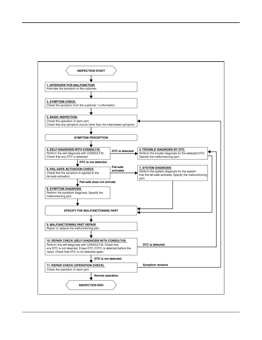
Work Flow
INFOID:0000000003773646
OVERALL SEQUENCE
DETAILED FLOW
1.
INTERVIEW FOR MALFUNCTION
Interview the symptom to the customer.
JPLIA0313GB