Nissan Teana J32. Manual - part 512
EXL-18
< FUNCTION DIAGNOSIS >
[XENON TYPE]
FRONT FOG LAMP SYSTEM
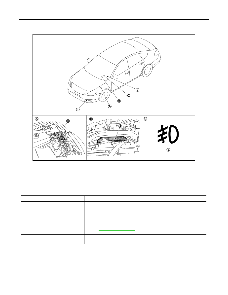
Component Parts Location
INFOID:0000000003773533
Component Description
INFOID:0000000003773534
1.
Front fog lamp
2.
Combination switch
3.
IPDM E/R
4.
BCM
5.
Front fog lamp indicator lamp
A.
Engine room (LH)
B.
Behind the combination meter
C.
On the combination meter
JPLIA1121ZZ
Part
Description
BCM
• Detects each switch condition by the combination switch reading function.
• Judges the front fog lamp ON/OFF status according to the vehicle condition.
- Requests the front fog lamp relay ON to IPDM E/R (with CAN communication).
IPDM E/R
Controls the integrated relay and supplies voltage to the load according to the request
from BCM (with CAN communication).
Combination switch
(Lighting & turn signal switch)
Refer to
.
Combination meter
(Front fog lamp indicator lamp)
Turn the front fog lamp indicator lamp ON according to the request from BCM (with
CAN communication).