Nissan Teana J32. Manual - part 493
EM-96
< DISASSEMBLY AND ASSEMBLY >
CYLINDER HEAD
CYLINDER HEAD
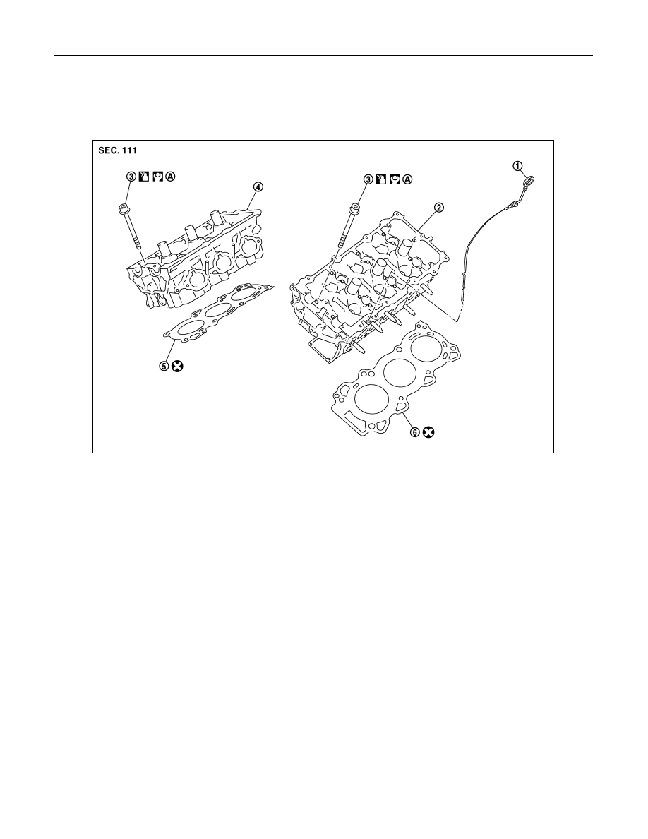
Exploded View
INFOID:0000000003802289
REMOVAL
DISASSEMBLY
1.
Oil level gauge
2.
Cylinder head (bank 2)
3.
Cylinder head bolt
4.
Cylinder head (bank 1)
5.
Cylinder head gasket (bank 1)
6.
Cylinder head gasket (bank 2)
A.
Refer to
Refer to
for symbols in the figure.
JPBIA1748ZZ