Nissan Teana J32. Manual - part 354
FRONT FENDER
DLK-199
< ON-VEHICLE REPAIR >
[WITH INTELLIGENT KEY SYSTEM]
C
D
E
F
G
H
I
J
L
M
A
B
DLK
N
O
P
FRONT FENDER
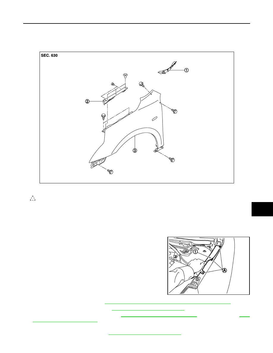
Exploded View
INFOID:0000000003813392
Removal and Installation
INFOID:0000000003813393
CAUTION:
Use a shop cloth to protect the body from being damaged during removal and installation.
REMOVAL
1.
Remove clips (A) of hood seal assembly (side) (1).
2.
Remove fender protector. Refer to
EXT-22, "FENDER PROTECTOR : Removal and Installation"
3.
Remove front bumper fascia. Refer to
EXT-12, "Removal and Installation"
.
4.
Remove front combination lamp. Refer to
EXL-181, "Removal and Installation"
(XENON TYPE) or
343, "Removal and Installation"
(HALOGEN TYPE).
5.
Remove front fender cover.
6.
Remove center mud guard. Refer to
EXT-26, "Removal and Installation"
1.
Front fender cover
2.
Hood seal assembly (side)
3.
Front fender
: Pawl
JMKIA2383ZZ
JMKIA2397ZZ