Nissan Teana J32. Manual - part 352


  Index      Nissan     Nissan Teana J32 (2008 year) - Service and Repair Manual


Search            


Content   ..  350  351  352  353   ..


Nissan Teana J32. Manual - part 352


HOOD

DLK-191

< ON-VEHICLE REPAIR >

[WITH INTELLIGENT KEY SYSTEM]

C

D

E

F

G

H

I

J

L

M

A

B

DLK

N

O

P

ON-VEHICLE REPAIR

HOOD

HOOD ASSEMBLY

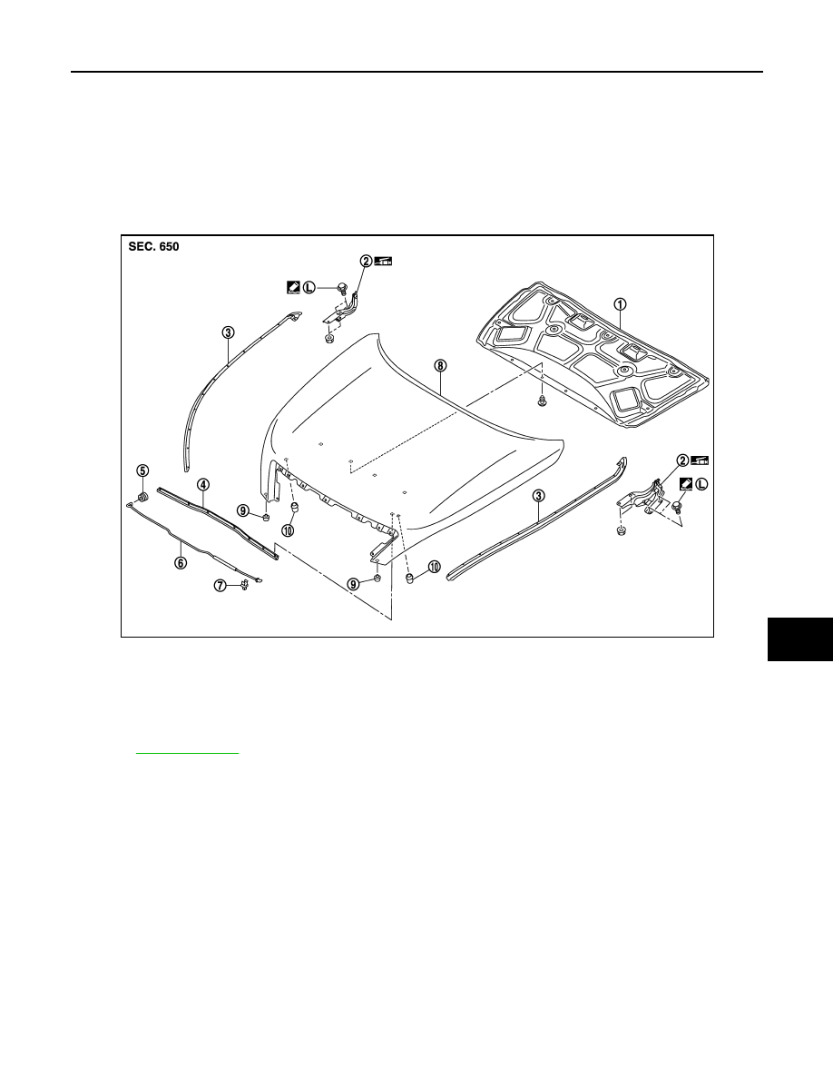
HOOD ASSEMBLY : Exploded View

INFOID:0000000003813383

REMOVAL

ADJUSTMENT

1.

Hood insulator

2.

Hood hinge (RH/LH)

3.

Hood seal (front) (RH/LH)

4.

Radiator core seal

5.

Grommet

6.

Hood support rod

7.

Clamp

8.

Hood assembly

9.

Hood bumper rubber (lower) (RH/
LH)

10. Hood bumper rubber (side) (RH/LH)

Refer to 

GI-4, "Components"

 for symbols in the figure.

JMKIA2380ZZ

DLK-192

< ON-VEHICLE REPAIR >

[WITH INTELLIGENT KEY SYSTEM]

HOOD

HOOD ASSEMBLY : Removal and Installation

INFOID:0000000003813384

CAUTION:

Operate with two workers, because of its heavy weight.

REMOVAL

1.

Remove hood insulator.

2.

Remove washer nozzle and washer tube. Refer to 

WW-102, "Removal and Installation"

.

3.

Support hood assembly with a proper material to prevent it from falling.

WARNING:

Bodily injury may occur if no supporting rod is holding the hood open when removing the hood
stay.

4.

Remove hood hinge mounting nuts on the hood to remove the hood assembly.

5.

Remove the following parts after removing the hood assembly.
• Radiator core seal
• Hood bumper rubber (lower, side)
• Hood seal (front)

1.

Hood assembly

2.

Hood bumper rubber

3.

Hood lock assembly

4.

Hood hinge

5.

Front bumper fascia

6.

Front combination lamp

7.

Front fender

Refer to 

GI-4, "Components"

 for symbols in the figure.

JMKIA2391GB

HOOD

DLK-193

< ON-VEHICLE REPAIR >

[WITH INTELLIGENT KEY SYSTEM]

C

D

E

F

G

H

I

J

L

M

A

B

DLK

N

O

P

• Front grille: Refer to 

EXT-18, "Removal and Installation"

.

INSTALLATION

Install in the reverse order of removal.

CAUTION:

• After installing, perform hood fitting adjustment. Refer to 

DLK-193, "HOOD ASSEMBLY : Adjust-

ment"

.

• After installing, perform front washer nozzle and tube inspection and adjustment. Refer to 

WW-102,

"Inspection and Adjustment"

.

HOOD ASSEMBLY : Adjustment

INFOID:0000000003813385

Check the clearance and the surface height between hood and each part visually and by touching. (Fitting
standard dimension in the table below should be satisfied.
If the clearance and the surface height are out of specification, adjust them according to the procedures
shown below.

Unit: mm (in)

1.

Remove hood lock and adjust the height by rotating hood bumper rubber (side, lower) until hood becomes
1 to1.5 mm (0.039 to 0.059 in) lower than fender.

2.

Temporarily tighten hood lock assembly, and position by engaging it with hood striker. Check hood lock
and striker for looseness and adjust the clearance and evenness with striker to satisfy the specification.

3.

Adjust A and B shown in the figure to the following value with hood's own weight by dropping it from
approximately 200 mm (7.874 in) height or by pressing hood lightly [approximately 29 N (3.0 kg, 6.5 lb)].

4.

After adjustment, tighten lock bolts to the specified torque.

HOOD HINGE

Portion

Standard

Difference

(RH/LH, MAX)

Hood – Front bumper 
fascia

A – A

D

Clearance

3.7 – 8.3

(0.146 – 0.315)

2.0

(0.079)

Hood – Front combina-
tion lamp

B – B

E

Clearance

2.4 – 6.8

(0.094 – 0.268)

2.5

(0.098)

Hood – Front fender

C – C

F

Clearance

3.1 – 6.1

(0.122 – 0.240)

2.0

(0.079)

G

Surface height

1.5 – 1.5

(

0.059 – 0.059)

1.

Hood striker

2.

Primary latch

3.

Secondary striker

4.

Secondary latch

A

: 20.0 mm (0.787 in)

B

: 6.8 mm (0.268 in)

JMKIA2399ZZ

DLK-194

< ON-VEHICLE REPAIR >

[WITH INTELLIGENT KEY SYSTEM]

HOOD

HOOD HINGE : Exploded View

INFOID:0000000003819555

HOOD HINGE : Removal and Installation

INFOID:0000000003813387

REMOVAL

1.

Remove hood assembly. Refer to 

DLK-192, "HOOD ASSEMBLY : Removal and Installation"

.

2.

Remove front fender. Refer to 

DLK-199, "Removal and Installation"

.

3.

Remove hood hinge mounting bolts, and then remove hood hinge.

INSTALLATION

Install in the reverse order of removal.

CAUTION:

• After installation, apply touch-up paint (the body color) onto the head of the hinge mounting bolts

and nuts.

• After installation, perform hood fitting adjustment. Refer to 

DLK-193, "HOOD ASSEMBLY : Adjust-

ment"

.

HOOD SUPPORT ROD

1.

Hood insulator

2.

Hood hinge (RH/LH)

3.

Hood seal (front) (RH/LH)

4.

Radiator core seal

5.

Grommet

6.

Hood support rod

7.

Clamp

8.

Hood assembly

9.

Hood bumper rubber (lower) (RH/
LH)

10.

Hood bumper rubber (side) (RH/LH)

Refer to 

GI-4, "Components"

 for symbols in the figure.

JMKIA2380ZZ


Content   ..  350  351  352  353   ..