Nissan Teana J32. Manual - part 353


  Index      Nissan     Nissan Teana J32 (2008 year) - Service and Repair Manual


Search            


Content   ..  351  352  353  354   ..


Nissan Teana J32. Manual - part 353


HOOD

DLK-195

< ON-VEHICLE REPAIR >

[WITH INTELLIGENT KEY SYSTEM]

C

D

E

F

G

H

I

J

L

M

A

B

DLK

N

O

P

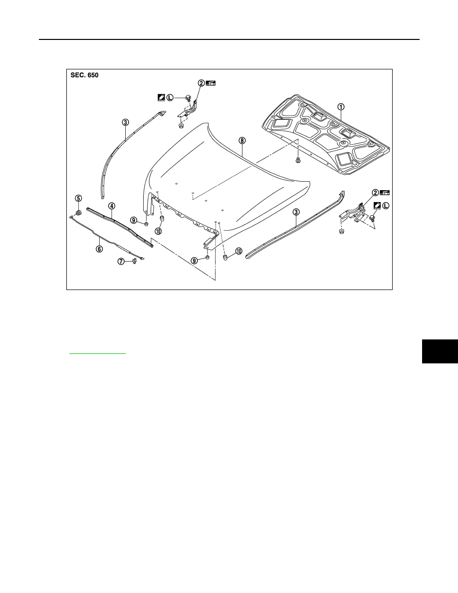
HOOD SUPPORT ROD : Exploded View

INFOID:0000000003819556

HOOD SUPPORT ROD : Removal and Installation

INFOID:0000000003813389

REMOVAL

1.

Support hood assembly with a proper material to prevent it from falling.

WARNING:

Bodily injury may occur if no supporting rod is holding the hood open when removing the hood
support rod.

2.

Pull hood support rod from grommet and remove.

INSTALLATION

Install in the reverse order of removal.

1.

Hood insulator

2.

Hood hinge (RH/LH)

3.

Hood seal (front) (RH/LH)

4.

Radiator core seal

5.

Grommet

6.

Hood support rod

7.

Clamp

8.

Hood assembly

9.

Hood bumper rubber (lower) (RH/
LH)

10.

Hood bumper rubber (side) (RH/LH)

Refer to 

GI-4, "Components"

 for symbols in the figure.

JMKIA2380ZZ

DLK-196

< ON-VEHICLE REPAIR >

[WITH INTELLIGENT KEY SYSTEM]

RADIATOR CORE SUPPORT

RADIATOR CORE SUPPORT

Exploded View

INFOID:0000000003795070

Removal and Installation

INFOID:0000000003795071

REMOVAL

1.

Use refrigerant collecting equipment to discharge the refrigerant. Refer to 

HA-24, "Collection and

Charge"

.

2.

Remove front under cover. Refer to 

EXT-28, "Removal and Installation"

.

3.

Drain engine coolant from radiator. Refer to 

CO-8, "Draining"

.

4.

Remove front bumper fascia, energy absorber and bumper reinforcement. Refer to 

EXT-12, "Removal

and Installation"

.

5.

Remove mounting clips and remove air duct cover.

6.

Remove hood lock opener and hood lock. Refer to 

DLK-220, "Removal and Installation"

.

7.

Disconnect connector of horn (HIGH/LOW), and then remove horn (HIGH/LOW). Refer to 

HRN-6,

"Removal and Installation"

.

8.

Disconnect connector of gas sensor, and then remove gas sensor (with intelligent air conditioner system).
Refer to 

VTL-82, "WITH INTELLIGENT AIR CONDITIONER SYSTEM : Removal and Installation"

.

9.

Remove bumper retainer assembly. Refer to 

EXT-12, "Removal and Installation"

.

10. Remove air guide (RH/LH).
11. Remove front combination lamp (RH/LH). Refer to 

EXL-181, "Removal and Installation"

 (XENON TYPE)

or 

EXL-343, "Removal and Installation"

 (HALOGEN TYPE).

12. Disconnect connector of ambient sensor. Refer to 

VTL-24, "Removal and Installation"

 (WITHOUT 7 INCH

DISPLAY) or 

VTL-81, "Removal and Installation"

 (WITH 7 INCH DISPLAY).

1.

Radiator upper hose bracket

2.

Hood switch bracket

3.

Air duct cover

4.

Air guide (RH/LH)

5.

Radiator core support

: Pawl

JMKIA2382ZZ

RADIATOR CORE SUPPORT

DLK-197

< ON-VEHICLE REPAIR >

[WITH INTELLIGENT KEY SYSTEM]

C

D

E

F

G

H

I

J

L

M

A

B

DLK

N

O

P

13. Disconnect connector of refrigerant pressure sensor. Refer to 

HA-50, "Exploded View"

.

14. Remove mounting bolt, and then remove engine coolant reservoir tank. Refer to 

CO-13, "Exploded View"

.

15. Remove mounting bolts, and then disconnect condenser pipe assembly. Refer to 

HA-48, "Exploded

View"

.

16. Remove condenser. Refer to 

HA-46, "Removal and Installation"

.

17. Remove mounting nut of radiator upper hose from radiator core support, and then remove radiator upper

hose and hood switch bracket. Refer to 

CO-25, "Exploded View"

.

18. Disconnect radiator upper hose from radiator pipe (upper). Refer to 

CO-25, "Exploded View"

.

19. Disconnect radiator lower hose (3). Refer to 

CO-25, "Exploded View"

.

20. Disconnect CVT fluid cooler hose on radiator side. Refer to 

TM-165, "Exploded View"

 (CVT: RE0F09B) or

TM-329, "Exploded View"

 (CVT: RE0F10A).

21. Remove power steering oil cooler pipe from radiator core sup-

port at point shown by arrows in the figure.

22. Disconnect connectors of the following parts.

• Cooling fan (RH/LH). Refer to 

CO-16, "Exploded View"

.

• Crash zone sensor. Refer to 

SR-18, "Removal and Installation"

.

23. Remove radiator upper clip. Refer to 

CO-13, "Exploded View"

.

24. Remove all harness clips from radiator core support.

CAUTION:

Never damage radiator.

25. Support hood assembly with a proper material to prevent it from falling.

WARNING:

Bodily injury may occur if no supporting rod is holding the hood open when removing the hood
stay.

26. Remove hood support rod. Refer to 

DLK-195, "HOOD SUPPORT ROD : Removal and Installation"

.

27. Remove mounting bolts, and then remove radiator core support.

CAUTION:

• Operate with two workers, because of its heavy weight.
• Never damage power steering oil cooler pipe.

28. Remove the following parts after removing radiator core support.

• Radiator lower hose, radiator upper hose, radiator pipe. Refer to 

CO-25, "Exploded View"

• Radiator. Refer to 

CO-13, "Exploded View"

.

• Cooling fan (RH/LH). Refer to 

CO-16, "Exploded View"

.

• Crash zone sensor. Refer to 

SR-18, "Exploded View"

.

• Power steering oil cooler pipe clip. Refer to 

ST-34, "Exploded View"

.

INSTALLATION

Install in the reverse order of removal.

JMKIA2395ZZ

: harness clip

JMKIA2396ZZ

DLK-198

< ON-VEHICLE REPAIR >

[WITH INTELLIGENT KEY SYSTEM]

RADIATOR CORE SUPPORT

CAUTION:

• After installation, inspection and replenish the following.
- Engine coolant. Refer to 

CO-8, "Inspection"

CO-9, "Refilling"

.

- CVT fluid. Refer to 

TM-142, "Inspection"

TM-143, "Changing"

 (CVT: RE0F09B) or 

TM-304, "Inspec-

tion"

TM-305, "Changing"

 (CVT: RE0F10A).

• After installation, adjust the following parts.
- Front combination lamp. 

EXL-174, "Aiming Adjustment Procedure (Low Beam)"

EXL-175, "Aiming

Adjustment Procedure (High Beam)"

 (XENON TYPE) or 

EXL-337, "Aiming Adjustment Procedure

(Low Beam)"

EXL-338, "Aiming Adjustment Procedure (High Beam)"

 (HALOGEN TYPE).


Content   ..  351  352  353  354   ..