Nissan Teana J32. Manual - part 274
BRC-154
< ON-VEHICLE REPAIR >
[VDC/TCS/ABS]
ABS ACTUATOR AND ELECTRIC UNIT (CONTROL UNIT)
ABS ACTUATOR AND ELECTRIC UNIT (CONTROL UNIT)
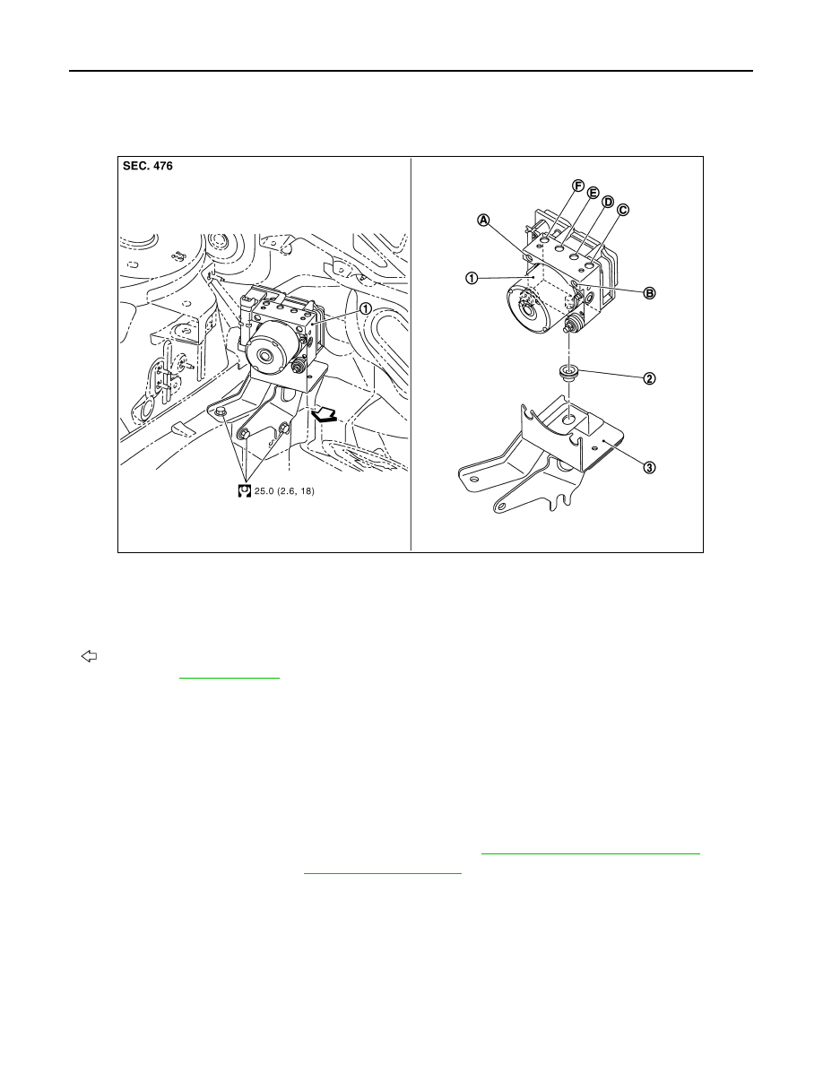
Exploded View
INFOID:0000000003767308
Removal and Installation
INFOID:0000000003767299
REMOVAL
CAUTION:
• Before servicing, disconnect the battery cable from negative terminal.
• To remove brake tube, use a flare nut wrench to prevent flare nuts and brake tube from being dam-
aged. To install, use flare nut crowfoot and torque wrench.
• Do not apply excessive impact to ABS actuator and electric unit (control unit), such as dropping it.
• Do not remove and install actuator by holding harness.
• After work is completed, bleed air from brake tube. Refer to
BR-10, "Bleeding Brake System"
1.
Remove cowl top cover. Refer to
.
2.
Disconnect ABS actuator and electric unit (control unit) connector.
3.
Loosen brake tube flare nuts, then remove brake tubes from ABS actuator and electric unit (control unit).
4.
Remove ABS actuator and electric unit (control unit) bracket mounting nuts.
5.
Remove ABS actuator and electric unit (control unit) from vehicle.
INSTALLATION
Note the following, and install in the reverse order of removal.
CAUTION:
• Before servicing, disconnect the battery cable from negative terminal.
1.
ABS actuator and electric unit (control
unit)
2.
Bushing
3.
Bracket
A.
From master cylinder secondary side B.
From master cylinder primary side
C.
To front LH brake caliper
D.
To rear RH brake caliper
E.
To rear LH brake caliper
F.
To front RH brake caliper
: Vehicle front
Refer to GI section
for symbol marks in the figure.
JSFIA0223GB