Content .. 1223 1224 1225 1226 ..
Nissan Teana J32. Manual - part 1225
VTL-86
< ON-VEHICLE REPAIR >
[WITH 7 INCH DISPLAY]
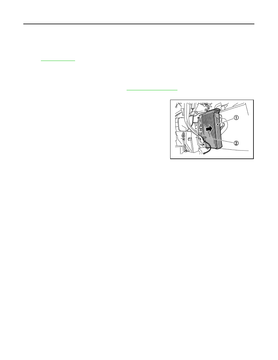
INTAKE SENSOR
Removal and Installation
INFOID:0000000003894498
REMOVAL
1.
Remove evaporator pipe assembly. Refer to
.
2.
Disconnect intake sensor connector.
3.
Slide evaporator (1) toward the right side of the vehicle (as
shown in the figure), and then remove intake sensor (2).
INSTALLATION
Installation is basically the reverse order of removal.
CAUTION:
• Replace O-rings with new ones. Then apply compressor oil to them when installing.
• Mark the mounting position of intake sensor bracket prior to removal so that the reinstalled sensor
can be located in the same position.
• Do not rotate the bracket insertion part when removing and installing the intake sensor.
• Check for refrigerant leakage when charging refrigerant.
37. Defroster door link
38.
Foot door link
39.
Max. cool door lever
40. Foot door lever
41.
Defroster door lever
42.
Adapter case
43. Distributor lower case
44.
Ventilator door
45.
Intake sensor
46. Intake sensor bracket
47.
Foot door
48.
Max. cool door
49. Defroster door
50.
Air mix door (Slide door)
for symbols in the figure.
JPIIA0907ZZ