Content .. 1211 1212 1213 1214 ..
Nissan Teana J32. Manual - part 1213
VTL-38
< ON-VEHICLE REPAIR >
[WITHOUT 7 INCH DISPLAY]
HEATER & COOLING UNIT ASSEMBLY
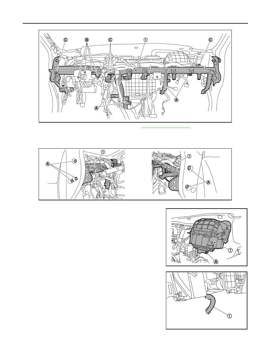
8.
Remove mounting bolts (A) from heater & cooling unit assembly and blower unit.
9.
Remove steering column mounting nuts (B). Refer to
10. Remove ground bolts (C) from steering member (1).
11. Disconnect each harness connectors, and remove harness clips from steering member.
12. Remove mounting bolts (A), and then remove steering member (1).
13. Disconnect the intake door motor and blower motor connectors.
14. Remove mounting screws (A), and then remove blower unit (1).
15. Disconnect drain hose (1) from heater & cooling unit assembly.
JPIIA0917ZZ
JPIIA0918ZZ
JPIIA0919ZZ
JPIIA0920ZZ