Nissan Teana J32. Manual - part 1128


  Index      Nissan     Nissan Teana J32 (2008 year) - Service and Repair Manual


Search            


Content   ..  1126  1127  1128  1129   ..


Nissan Teana J32. Manual - part 1128


TM-36

< FUNCTION DIAGNOSIS >

[CVT: RE0F09B]

ON BOARD DIAGNOSTIC (OBD) SYSTEM

Only one set of freeze frame data (either 1st trip freeze frame data or freeze frame data) can be stored in the
ECM. 1st trip freeze frame data is stored in the ECM memory along with the 1st trip DTC. There is no priority
for 1st trip freeze frame data, and it is updated each time a different 1st trip DTC is detected. However, once
freeze frame data (2nd trip detection/MI on) is stored in the ECM memory, 1st trip freeze frame data is no
longer stored. Remember, only one set of freeze frame data can be stored in the ECM. The ECM has the fol-
lowing priorities to update the data.

Both 1st trip freeze frame data and freeze frame data (along with the DTC) are cleared when the ECM mem-
ory is erased.

How to Erase DTC

• The diagnostic trouble code can be erased by CONSULT-III, GST or ECM DIAGNOSTIC TEST MODE as

described below.

If the battery cable is disconnected, the diagnostic trouble code will be lost within 24 hours.
When erasing the DTC, using CONSULT-III or GST is easier and quicker than switching the mode

selector on the ECM.

• The following emission-related diagnostic information is cleared from the ECM memory when erasing DTC

related to OBD. For details, refer to 

EC-389, "DTC Index"

.

Diagnostic trouble codes (DTC)
1st trip diagnostic trouble codes (1st trip DTC)
Freeze frame data
1st trip freeze frame data
System readiness test (SRT) codes
Test values

How to Erase DTC (With CONSULT-III)

The emission related diagnostic information in the TCM and ECM can be erased by selecting “ALL Erase” in
the “Description” of “FINAL CHECK” mode with CONSULT-III.

How to Erase DTC (With GST)

1.

If the ignition switch stays ON after repair work, be sure to turn ignition switch OFF once. Wait at least 10
seconds and then turn it ON (engine stopped) again.

2.

Select Mode 4 with GST (Generic Scan Tool). For details, refer to 

EC-113, "CONSULT-III Function"

.

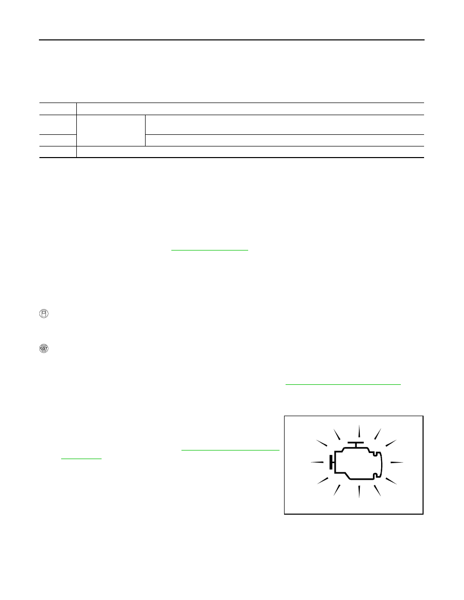
MALFUNCTION INDICATOR (MI)

Description

The MI is located on the instrument panel.

1.

The MI is turned ON when the ignition switch is turned ON with-
out the engine running. This is a bulb check.
• If the MI is not turned ON, refer to 

EC-346, "Component Func-

tion Check"

.

2.

The MI is turned OFF when the engine is started.
If the MI remains ON, the on board diagnostic system has
detected an engine system malfunction.

Priority

Items

1

Freeze frame data

Misfire — DTC: P0300 - P0306
Fuel Injection System Function — DTC: P0171, P0172, P0174, P0175

2

Except the above items (Includes CVT related items)

3

1st trip freeze frame data

SAT652J

DIAGNOSIS SYSTEM (TCM)

TM-37

< FUNCTION DIAGNOSIS >

[CVT: RE0F09B]

C

E

F

G

H

I

J

K

L

M

A

B

TM

N

O

P

DIAGNOSIS SYSTEM (TCM)

CONSULT-III Function (TRANSMISSION)

INFOID:0000000003848944

FUNCTION

CONSULT-III can display each diagnostic item using the diagnostic test modes shown following.

WORK SUPPORT MODE

Display Item List

Engine Brake Adjustment

CAUTION:

Mode of “+1”“0”“

1”“

2”“OFF” can be selected by touching “UP”or “DOWN” on CONSULT-III screen.

However, do not select a mode other than “0” and “OFF”. Selecting “+1” or “

1” or “–2” may cause

irregular driveability.

Check CVT Fluid Deterioration Date

CAUTION:

Touch “CLEAR” after changing CVT fluid, and then erase “CVTF DETERIORATION DATE”.

SELF-DIAGNOSTIC RESULT MODE

Display Items List

Refer to 

TM-121, "DTC Index"

.

DATA MONITOR MODE

Display Items List

Diagnostic test mode

Function

Work Support

This mode enables a technician to adjust some devices faster and more accurately.

Self-Diagnostic Results

Retrieve DTC from ECU and display diagnostic items.

Data Monitor

Monitor the input/output signal of the control unit in real time.

CAN Diagnosis

This mode displays a network diagnosis result about CAN by a diagram.

CAN Diagnostic Support Monitor

It monitors the status of CAN communication.

Function Test

This mode can show results of self-diagnosis of ECU with either “OK” or “NG”. For en-
gine, more practical tests regarding sensors/switches and/or actuators are available.

ECU Identification

Display the ECU identification number (part number etc.) of the selected system.

Special Function

Other results or histories, etc. that are recorded in ECU are displayed.

Item name

Description

ENGINE BRAKE ADJ.

The engine brake level setting can be canceled.

CONFORM CVTF DETERIORTN

The CVT fluid deterioration level can be checked.

“ENGINE BRAKE LEVEL”

0

: Initial set value (Engine brake level control is activated)

OFF

: Engine brake level control is deactivated.

“CVTF DETERIORATION DATE”

More than 210000

: It is necessary to change CVT fluid.

Less than 210000

: It is not necessary to change CVT fluid.

TM-38

< FUNCTION DIAGNOSIS >

[CVT: RE0F09B]

DIAGNOSIS SYSTEM (TCM)

 X: Standard, —: Not applicable, 

: Option

Monitored item (Unit)

Monitor item selection

Remarks

 ECU IN-

PUT SIG-

NALS

MAIN SIG-

NALS

SELEC-

TION 

FROM 
MENU

VSP SENSOR (km/h)

X

Output speed sensor (secondary speed sensor)

ESTM VSP SIG (km/h)

X

PRI SPEED SEN (rpm) 

X

ENG SPEED SIG (rpm) 

X

SEC HYDR SEN (V)

X

PRI HYDR SEN (V)

X

ATF TEMP SEN (V)

X

CVT fluid temperature sensor

VIGN SEN (V)

 X

VEHICLE SPEED (km/h or mph)

X

Vehicle speed recognized by the TCM.

PRI SPEED (rpm)

X

Primary pulley speed

SEC SPEED (rpm)

Secondary pulley speed

ENG SPEED (rpm) 

X

SLIP REV (rpm)

X

Difference between engine speed and primary 
pulley speed.

GEAR RATIO

X

G SPEED (G)

ACC PEDAL OPEN (0.0/8)

X

X

Degree of opening for accelerator recognized by 
the TCM.
For fail-safe operation, the specific value used for 
control is displayed.

TRQ RTO

SEC PRESS (MPa)

X

PRI PRESS (MPa)

X

ATFTEMP COUNT

X

Means CVT fluid temperature. Actual oil temper-
ature 

°

C (

°

F) cannot be checked unless a numeric 

value is converted. Refer to 

TM-139

.

DSR REV (rpm)

DGEAR RATIO

DSTM STEP (step)

STM STEP (step)

X

LU PRS (MPa)

LINE PRS (MPa)

TGT SEC PRESS (MPa)

ISOLT1 (A)

X

Torque converter clutch solenoid valve output 
current

ISOLT2 (A)

X

Pressure control solenoid valve A (line pressure 
solenoid valve) output current

ISOLT3 (A)

X

Pressure control solenoid valve B (secondary 
pressure solenoid valve) output current

DIAGNOSIS SYSTEM (TCM)

TM-39

< FUNCTION DIAGNOSIS >

[CVT: RE0F09B]

C

E

F

G

H

I

J

K

L

M

A

B

TM

N

O

P

SOLMON1 (A)

X

X

Torque converter clutch solenoid valve monitor 
current

SOLMON2 (A)

X

X

Pressure control solenoid valve A (line pressure 
solenoid valve) monitor current

SOLMON3 (A)

X

X

Pressure control solenoid valve B (secondary 
pressure solenoid valve) monitor current

INH SW3M (On/Off)

X

PNP switch 3 ON-OFF status monitor

INH SW4 (On/Off)

X

PNP switch 4 ON-OFF status

INH SW3 (On/Off)

X

PNP switch 3 ON-OFF status

INH SW2 (On/Off)

X

PNP switch 2 ON-OFF status

INH SW1 (On/Off)

X

PNP switch 1 ON-OFF status

BRAKE SW (On/Off)

X

X

Stop lamp switch (signal input via CAN communi-
cations)

FULL SW (On/Off)

X

X

Signal input via CAN communications

IDLE SW (On/Off)

X

X

SPORT MODE SW (On/Off)

X

X

STRDWNSW (On/Off)

X

Not mounted but displayed.

STRUPSW (On/Off)

X

DOWNLVR (On/Off)

X

UPLVR (On/Off)

X

NONMMODE (On/Off)

X

MMODE (On/Off)

X

INDLRNG (On/Off)

“L” position indicator output

INDDRNG (On/Off)

“D” position indicator output

INDNRNG (On/Off)

“N” position indicator output

INDRRNG (On/Off)

“R” position indicator output

INDPRNG (On/Off)

“P” position indicator output

CVT LAMP (On/Off)

SPORT MODE IND (On/Off)

MMODE IND (On/Off)

Not mounted but displayed.

SMCOIL D (On/Off)

Step motor coil “D” energizing status

SMCOIL C (On/Off)

Step motor coil “C” energizing status

SMCOIL B (On/Off)

Step motor coil “B” energizing status

SMCOIL A (On/Off)

Step motor coil “A” energizing status

LUSEL SOL OUT (On/Off)

REV LAMP (On/Off)

 X

STRTR RLY OUT (On/Off)

Starter relay

Monitored item (Unit)

Monitor item selection

Remarks

 ECU IN-

PUT SIG-

NALS

MAIN SIG-

NALS

SELEC-

TION 

FROM 
MENU


Content   ..  1126  1127  1128  1129   ..