Nissan Teana J32. Manual - part 1127


  Index      Nissan     Nissan Teana J32 (2008 year) - Service and Repair Manual


Search            


Content   ..  1125  1126  1127  1128   ..


Nissan Teana J32. Manual - part 1127


TM-32

< FUNCTION DIAGNOSIS >

[CVT: RE0F09B]

SHIFT CONTROL SYSTEM

*1: Primary pressure sensor is included in CVT assembly.

*2: Control valve assembly is included in CVT assembly.

NOTE:
The following components are included in control valve assembly (7).
• PNP switch
• Primary speed sensor
• Step motor
• Secondary pressure solenoid valve
• Line pressure solenoid valve
• Torque converter clutch solenoid valve
• Shift control valve
• Secondary valve
• Manual valve
• Lock-up select solenoid valve
• CVT fluid temperature sensor
• Secondary pressure sensor
• ROM  assembly

Component Description

INFOID:0000000003848939

TRANSAXLE ASSEMBLY

EXCEPT TRANSAXLE ASSEMBLY

1.

Sport mode switch

2.

Shift position indicator

3.

SPORT indicator lamp

4.

TCM

5.

Secondary speed sensor

6.

Primary pressure sensor

*1

7.

Control valve assembly

*2

8.

CVT unit connector

9.

Accelerator pedal position sensor

A.

Control device

B.

Combination meter

C.

Engine room LH

D.

CVT assembly

E.

Accelerator pedal, upper
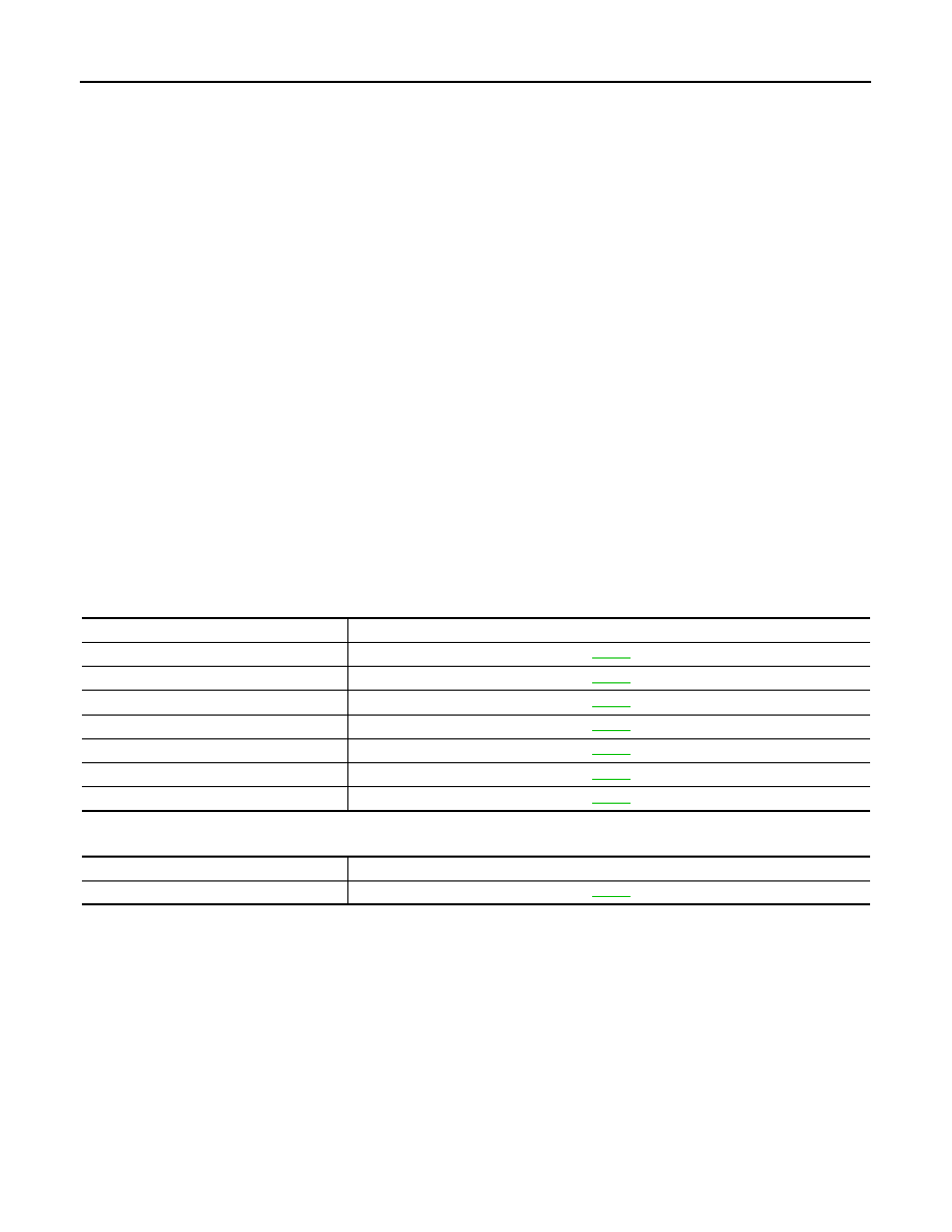
Item

Function

PNP switch

TM-47

Primary speed sensor

TM-52

Secondary speed sensor

TM-55

Step motor

TM-97

Shift control valve

TM-22

Primary pulley

TM-19

Secondary pulley

TM-19

Item

Function

TCM

TM-22

SHIFT LOCK SYSTEM

TM-33

< FUNCTION DIAGNOSIS >

[CVT: RE0F09B]

C

E

F

G

H

I

J

K

L

M

A

B

TM

N

O

P

SHIFT LOCK SYSTEM

System Description

INFOID:0000000003848940

The shift lever cannot be shifted from the “P” position unless the
brake pedal is depressed while the ignition switch is set to ON. The
shift lock is unlocked by turning the shift lock solenoid ON when the
ignition switch is set to ON, the park position switch is turned ON
(selector lever is in “P” position), and the stop lamp switch is turned
ON (brake pedal is depressed) as shown in the operation chart in the
figure. Therefore, the shift lock solenoid receives no ON signal and
the shift lock remains locked if all of the above conditions are not ful-
filled. (However, selector operation is allowed if the shift lock release
button is pressed.)

SHIFT LOCK OPERATION at “P” POSITION

When Brake Pedal Is Not Depressed (No Selector Operation Allowed)

The shift lock solenoid (A) is turned OFF (not energized) and the
solenoid rod (B) is extended with the spring when the brake pedal is
not depressed (no selector operation allowed) with the ignition
switch ON.
The connecting lock lever (C) is located at the position shown in the
figure when the solenoid rod is extended. It prevents the movement
of the detent rod (D). The selector lever cannot be shifted from the
“P” position for this reason. 

When Brake Pedal Is Depressed (Shift Operation Allowed)

The shift lock solenoid (A) is turned ON (energized) when the brake
pedal is depressed with the ignition switch ON. The solenoid rod (B)
is compressed by the electromagnetic force. The connecting lock
lever (C) rotates when the solenoid is activated. Therefore, the
detent rod (D) can be moved. The selector lever can be shifted to
other positions for this reason. 

“P” POSITION HOLD MECHANISM (IGNITION SWITCH LOCK)

JPDIA0624GB

JPDIA0612ZZ

JPDIA0613ZZ

TM-34

< FUNCTION DIAGNOSIS >

[CVT: RE0F09B]

SHIFT LOCK SYSTEM

The shift lock solenoid (A) is not energized when the ignition switch
is in any position other than ON. In this condition, the shift mecha-
nism is locked and “P” position is held. The operation cannot be per-
formed from “P” position if the brake pedal is depressed with the
ignition switch ON when the operation system of shift lock solenoid is
malfunctioning. However, the lock lever (B) is forcibly rotated and the
shift lock is released when the shift lock release button (C) is
pressed from above. Then the selector operation from “P” position
can be performed. 

CAUTION:

Use the shift lock release button only when the selector lever cannot be operated even if the brake
pedal is depressed with the ignition switch ON. 

Component Parts Location

INFOID:0000000003848941

Component Description

INFOID:0000000003848942

SHIFT LOCK

D

: Detent rod

JPDIA0614ZZ

1.

Stop lamp switch

A.

Shift lock release button

B.

Shift lock solenoid

C.

Park position switch

JPDIA0753ZZ

Component

Function

Shift lock solenoid

TM-103

Lock lever

Detent rod

Park position switch

Shift lock release button

ON BOARD DIAGNOSTIC (OBD) SYSTEM

TM-35

< FUNCTION DIAGNOSIS >

[CVT: RE0F09B]

C

E

F

G

H

I

J

K

L

M

A

B

TM

N

O

P

ON BOARD DIAGNOSTIC (OBD) SYSTEM

Diagnosis Description

INFOID:0000000003848943

DESCRIPTION

The CVT system has two self-diagnostic systems.
The first is the emission-related on board diagnostic system (OBD) performed by the TCM in combination with
the ECM. A malfunction is indicated by the MI (Malfunction Indicator) and is stored as a DTC in the ECM mem-
ory and in the TCM memory.
The second is the TCM original self-diagnosis performed by the TCM. A malfunction history is stored in the
TCM memory. The detected items are overlapped with OBD self-diagnostic items. For details, refer to 

TM-121,

"DTC Index"

.

OBD FUNCTION

The ECM provides emission-related on board diagnostic (OBD) functions for the CVT system. One function is
to receive a signal from the TCM used with OBD-related parts of the CVT system. The signal is sent to the
ECM when a malfunction occurs in the corresponding OBD-related part. The other function is to indicate a
diagnostic result by means of the MI (Malfunction Indicator) on the instrument panel. Sensors, switches and
solenoid valves are used as sensing elements.
The MI automatically illuminates in “One or Two Trip Detection Logic” when a malfunction is sensed in relation
to CVT system parts.

ONE OR TWO TRIP DETECTION LOGIC OF OBD

One Trip Detection Logic

If a malfunction is sensed during the first test drive, the MI illuminates and the ECM memory stores the mal-
function as a DTC. The TCM is not provided with such a memory function.

Two Trip Detection Logic

When a malfunction is sensed during the first test drive, it is stored in the ECM memory as a 1st trip DTC
(diagnostic trouble code) or 1st trip freeze frame data. At this point, the MI does not illuminate. — 1st trip
If the same malfunction as that experienced during the first test drive is sensed during the second test drive,
the MI will illuminate. — 2nd trip
The “trip” in the “One or Two Trip Detection Logic” means a driving mode in which self-diagnosis is performed
during vehicle operation.

OBD DIAGNOSTIC TROUBLE CODE (DTC)

How to Read DTC and 1st Trip DTC

DTC and 1st trip DTC can be read by the following methods.
(

 with CONSULT-III or 

 GST) CONSULT-III or GST (Generic Scan Tool) Examples: P0705, P0720, etc.

These DTC are prescribed by ISO 15031-6.
(CONSULT-III also displays the malfunctioning component or system.)
• 1st trip DTC No. is the same as DTC No.
• Output of the diagnostic trouble code indicates that the indicated circuit has a malfunction. How-

ever, in case of the Mode II and GST, they do not indicate whether the malfunction is still occurring or
it occurred in the past and has returned to normal.
CONSULT-III can identify them as shown below, therefore, CONSULT-III (if available) is recom-
mended.

- DTC or 1st trip DTC of a malfunction is displayed in “Self-Diagnostic Results” mode for “ENGINE” with CON-

SULT-III. Time data indicates how many times the vehicle was driven after the last detection of a DTC.

- If the DTC is being detected currently, the time data will be “0”.
- If a 1st trip DTC is stored in the ECM, the time data will be “1t”.

Freeze Frame Data and 1st Trip Freeze Frame Data

• The ECM has a memory function, which stores the driving conditions such as fuel system status, calculated

load value, engine coolant temperature, short-term fuel trim, long-term fuel trim, engine speed and vehicle
speed at the moment the ECM detects a malfunction.
Data that are stored in the ECM memory, along with the 1st trip DTC, are called 1st trip freeze frame data,
and the data, stored together with the DTC data, are called freeze frame data and displayed on CONSULT-
III or GST. The 1st trip freeze frame data can only be displayed on the CONSULT-III screen, not on the GST.
For details, refer to 

EC-113, "CONSULT-III Function"

.


Content   ..  1125  1126  1127  1128   ..