Content .. 1059 1060 1061 1062 ..
Nissan Teana J32. Manual - part 1061
DISPOSAL OF AIR BAG MODULE AND SEAT BELT PRE-TENSIONER
SR-27
< ON-VEHICLE REPAIR >
C
D
E
F
G
I
J
K
L
M
A
B
SR
N
O
P
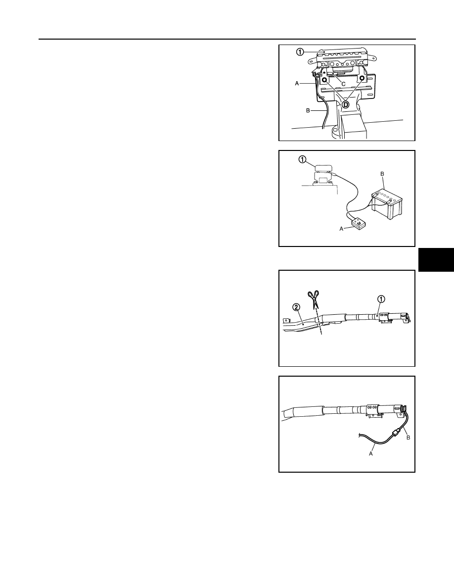
2.
Firmly secure air bag module bracket (SST: KV99105300) (A) in
a vise.
3.
Insert two bolts (D) through air bag module bracket and air bag
module lower side holes, and fix then with two nuts.
4.
Connect deployment tool (SST: KV99106400) (B) and deploy-
ment tool adapter (SST: KV99110500) (C) to front passenger air
bag module (1).
5.
Connect red clip of deployment tool (A) to battery positive termi-
nal and black clip to negative terminal (B).
6.
The lamp on the right side of the tool, marked “deployment tool
power”, should illuminate green, not red.
7.
Press the button on the deployment tool (A). The left side lamp
on the tool, marked “air bag connector voltage”, will illuminate
and the air bag module (1) will deploy.
CAUTION:
• When deploying the front passenger air bag module,
never stand on the deploying side.
• Stand at least 5.0 m (16.4 ft) away from the air bag module.
Side Curtain Air Bag Module
1.
Cut the inflator (1) from side curtain air bag module (2).
2.
Connect deployment tool (SST: KV99106400) (A) and deploy-
ment tool adapter (SST: KV99110500) (B) to the inflator.
JMHIA0631ZZ
JMHIA0209ZZ
JMHIA0282ZZ
JMHIA0283ZZ