Nissan Teana J32. Manual - part 1058


  Index      Nissan     Nissan Teana J32 (2008 year) - Service and Repair Manual


Search            


Content   ..  1056  1057  1058  1059   ..


Nissan Teana J32. Manual - part 1058


SIDE CURTAIN AIR BAG MODULE

SR-15

< ON-VEHICLE REPAIR >

C

D

E

F

G

I

J

K

L

M

A

B

SR

N

O

P

3.

Remove fixing bolts, and then remove side curtain air bag module.
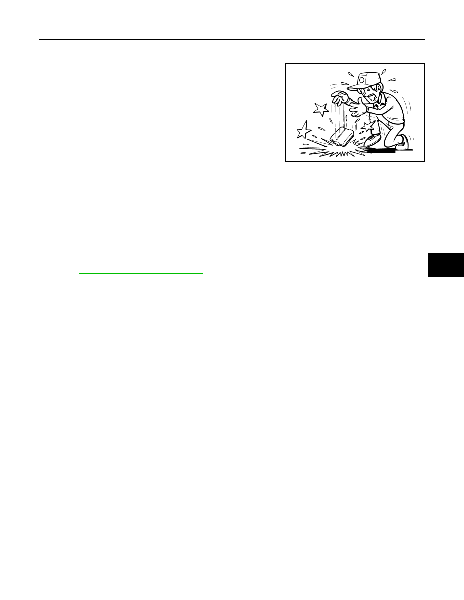
CAUTION:

• Never impact the side curtain air bag module.
• Replace the side curtain air bag module if it has been dropped

or sustained an impact. 

• Never insert any foreign objects (screwdriver, etc.) into side curtain air bag module.
• Never disassemble side curtain air bag module.
• Never expose the side curtain air bag module to temperatures exceeding 90

°

C (194

°

F).

• Never allow oil, grease, detergent or water to come in contact with the side curtain air bag module.

INSTALLATION

Install in the reverse order of removal.

CAUTION:

• In the case that a malfunction is detected by the air bag warning lamp, after repair or replacement of

the malfunctioning parts, reset the memory by self-diagnosis or by CONSULT-III.

• After the work is completed, check that no system malfunction is detected by air bag warning lamp.

Refer to 

SRC-10, "Diagnosis Description"

.

JMHIA0009ZZ

SR-16

< ON-VEHICLE REPAIR >

FRONT SIDE AIR BAG MODULE

FRONT SIDE AIR BAG MODULE

Exploded View

INFOID:0000000003857353

Removal and Installation

INFOID:0000000003857354

REMOVAL

WARNING:

• Before servicing, turn ignition switch OFF, disconnect battery negative terminal and wait at least 3

minutes.

• Always work from the rear of air bag module.
• Never use air tools or electric tools for servicing.
1.

Remove the front seat.
• With VENTILATION SEAT: Refer to 

SE-92, "Removal and Installation"

.

• Without VENTILATION SEAT: Refer to 

SE-135, "Removal and Installation"

.

2.

Remove the seatback trim and pad.
• With VENTILATION SEAT: Refer to 

SE-93, "Disassembly and Assembly"

.

• Without VENTILATION SEAT: Refer to 

SE-135, "Disassembly and Assembly"

.

3.

Remove the seatback finisher fixing screws, and then remove seatback finisher.

4.

Disconnect the front side air bag harness connector and harness clips.

5.

Remove the side air bag module fixing nut, and then remove side air bag module.

CAUTION:

1.

Seat frame assembly

2.

Side air bag module bracket

3.

Side air bag module

4.

Seatback finisher

Refer to 

GI-4, "Components"

 for symbols in the figure.

JMHIA0649GB

FRONT SIDE AIR BAG MODULE

SR-17

< ON-VEHICLE REPAIR >

C

D

E

F

G

I

J

K

L

M

A

B

SR

N

O

P

• Always place front side air bag module with pad side facing

upward.

• Never impact the air bag module.
• Replace the air bag module if it has been dropped or sus-

tained an impact. 

• Never insert any foreign objects (screwdriver, etc.) into front side air bag module.
• Never disassemble front side air bag module.
• Never expose the air bag module to temperatures exceeding 90

°

C (194

°

F).

• Never allow oil, grease, detergent or water to come in contact with the air bag module.

INSTALLATION

Install in the reverse order of removal.

CAUTION:

• Never use old fixing nut after removal; replace with new nut.
• Never damage the air bag harness.
• If any malfunction is detected by the air bag warning lamp, reset by the self-diagnosis function and

delete the memory by CONSULT-III.

• If any malfunction is still detected after the above operations, perform self-diagnosis to repair mal-

functions. 

• After the work is completed, check that no system malfunction is detected by air bag warning lamp.

Refer to 

SRC-10, "Diagnosis Description"

.

: Upward

JMHIA0274ZZ

JMHIA0009ZZ

SR-18

< ON-VEHICLE REPAIR >

CRASH ZONE SENSOR

CRASH ZONE SENSOR

Exploded View

INFOID:0000000003838673

Removal and Installation

INFOID:0000000003838674

WARNING:

• Before servicing, turn ignition switch OFF, disconnect battery negative terminal and wait at least 3

minutes.

• Never use air tools or electric tools for servicing.

REMOVAL

1.

Remove the air duct (inlet). Refer to 

EM-26, "Removal and Installation"

.

2.

Remove radiator hose clamp (1) mounting nut (A). 

1.

Crash zone sensor

: Vehicle front

Refer to 

GI-4, "Components"

 for symbols in the figure.

JMHIA0624GB

: Vehicle front

JMHIA0632ZZ


Content   ..  1056  1057  1058  1059   ..