Nissan Murano Z51. Manual - part 782


  Главная      Nissan     Nissan Murano Z51 (2010 year) - Service Manual


поиск по сайту            


содержание   ..  780  781  782  783   ..


Nissan Murano Z51. Manual - part 782


FRONT DRIVE SHAFT

FAX-21

< REMOVAL AND INSTALLATION >

[2WD]

C

E

F

G

H

I

J

K

L

M

A

B

FAX

N

O

P

WHEEL SIDE : Disassembly and Assembly

INFOID:0000000005518960

DISASSEMBLY

1.

Fix shaft with a vise.

CAUTION:

Protect shaft when fixing with a vise using aluminum or copper plates.

2.

Remove boot bands, and then remove boot from joint sub-assembly.
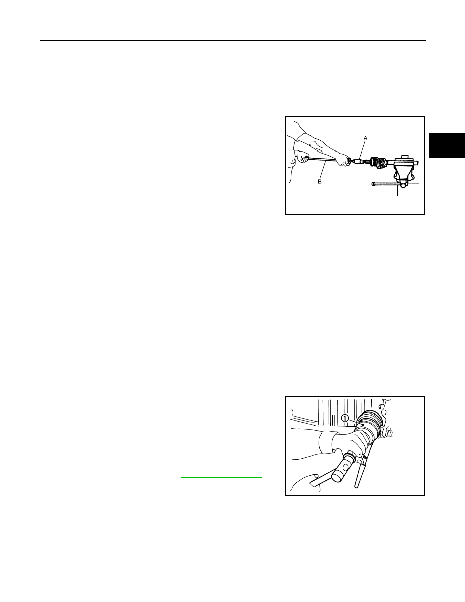
3.

Screw drive shaft puller (A) into joint sub-assembly screw part to
a length of 30 mm (1.18 in) or more. Support drive shaft with one
hand and pull out joint sub-assembly with a sliding hammer (B)
from housing assembly.

CAUTION:

• Align a sliding hammer and drive shaft and remove them

by pulling firmly and uniformly.

• If joint sub-assembly cannot be pulled out, try after

removing drive shaft from vehicle.

4.

Remove circular clip (1) from housing assembly.

5.

Remove boot from housing assembly.

ASSEMBLY

1.

Clean the old grease on joint sub-assembly with paper waste.

2.

Fill serration slot joint sub-assembly with NISSAN genuine grease or equivalent until the serration slot and
ball groove become full to the brim.

CAUTION:

After applying grease, use a paper waste to wipe off old grease that has oozed out.

3.

Install boot and boot bands to housing assembly.

CAUTION:

• Wrap serration on housing assembly with tape to protect the boot from damage.
• Never reuse boot and boot band.

4.

Remove the tape wrapped around the serration on housing assembly.

5.

Position the circular clip on groove at the housing assembly edge.

CAUTION:

Never reuse circular clip.
NOTE:
Drive joint inserter is recommended when installing circular clip.

6.

Align both center axles of the housing assembly edge and joint sub-assembly. Then assemble housing
assembly with joint sub-assembly holding circular clip.

7.

Install joint sub-assembly (1) to housing assembly using plastic
hammer.

CAUTION:

Confirm that joint sub-assembly is correctly engaged while
rotating drive housing assembly.

8.

Apply the specified amount of grease into the boot inside from
large diameter side of boot.

JPDIF0015ZZ

Grease amount

: Refer to 

FAX-28, "Drive Shaft"

.

JPDIF0011ZZ

FAX-22

< REMOVAL AND INSTALLATION >

[2WD]

FRONT DRIVE SHAFT

9.

Install the boot securely into grooves (indicated by “*” marks)
shown in the figure.

CAUTION:

If grease adheres to the boot mounting surface (indicated
by “*” mark) on the housing assembly or joint sub-assem-
bly, boot may be removed. Remove all grease from the boot
mounting surface.

10. To prevent the deformation of the boot, adjust the boot installa-

tion length (L) to the specified value shown below by inserting
the suitable tool into inside of the boot from the large diameter
side of the boot and discharging the inside air.

CAUTION:

• If the boot mounting length exceeds the standard, it may cause breakage of boot.
• Be careful not to touch the inside of the boot with a tip of tool.

11. Secure the large and small ends of the boot with boot bands

using the boot band crimping tool (A) [SST: KV40107300 (

)].

CAUTION:

Never reuse boot band.

NOTE:
Secure boot band so that dimension (A) meets the specification
as shown in the figure.

12. Secure joint sub-assembly and housing assembly, and then

make sure that they are in the correct position when rotating
boot. Reinstall them using boot bands when boot installation
positions become incorrect.

CAUTION:

Never reuse boot band.

TRANSAXLE SIDE

TRANSAXLE SIDE : Disassembly and Assembly

INFOID:0000000005518961

DISASSEMBLY

Left Side

1.

Fix drive shaft with a vise.

CAUTION:

Protect shaft using aluminum or copper plates when fixing with a vise.

2.

Disassemble boot (wheel side). Refer to 

FAX-21, "WHEEL SIDE : Disassembly and Assembly"

.

3.

Remove boot bands and boot (transaxle side).

Right Side

1.

Fix drive shaft with a vise.

CAUTION:

Protect shaft using aluminum or copper plates when fixing with a vise.

2.

Disassemble boot (wheel side). Refer to 

FAX-21, "WHEEL SIDE : Disassembly and Assembly"

.

L

: Refer to 

FAX-28, "Drive Shaft"

.

JPDIF0222ZZ

JPDIF0012ZZ

A

: 7.0 mm (0.276 in) or less

JPDIF0268ZZ

FRONT DRIVE SHAFT

FAX-23

< REMOVAL AND INSTALLATION >

[2WD]

C

E

F

G

H

I

J

K

L

M

A

B

FAX

N

O

P

3.

Remove boot bands and boot (transaxle side).

4.

Remove support bearing, follow the procedure described below. 

a.

Remove dust shield.

b.

Remove snap ring (1).

c.

Press out bearing housing and support bearing from housing
assembly.

d.

Remove dust shield.

e.

Remove snap ring (1).

JPDIF0121ZZ

JPDIF0073ZZ

SFA693

JPDIF0177ZZ

FAX-24

< REMOVAL AND INSTALLATION >

[2WD]

FRONT DRIVE SHAFT

f.

Press out support bearing from bearing housing (1) with suitable
drift (A) [SST: ST35271000 (

 )].

5.

Remove dynamic damper, follow the procedure described
below. 

a.

Remove damper bands.

b.

Remove dynamic damper from shaft.

ASSEMBLY

Left Side

1.

Install dust shield.

CAUTION:

Never reuse dust shield.

2.

Install circular clip.

CAUTION:

Never reuse circular clip.

3.

Clean old grease on housing assembly with paper waste.

4.

Install boot securely into grooves (indicated by “*” marks) shown
in the figure.

CAUTION:

If grease adheres to the boot mounting surface (indicated
by “*” mark) on housing assembly, boot may be removed.
Remove all grease from the boot mounting surface.

5.

To prevent the deformation of the boot, adjust the boot installa-
tion length (L) to the specified value shown below by inserting
the suitable tool into the inside of boot from the large diameter
side of boot and discharging inside air.

CAUTION:

• If the boot installation length exceeds the standard, it may cause breakage of boot.
• Be careful not to touch the inside of the boot with the tip of tool.

6.

Install boot bands securely as shown in the figure.

a.

Put boot band in the groove on drive shaft boot. Then fit pawls
(

) into holes to temporary installation.

NOTE:
For the large diameter side, fit projection (A) and guide slit (B) at
first.

JPDIF0151ZZ

L

:  Refer  to 

FAX-28, "Drive Shaft"

.

JPDIF0144ZZ

JPDIF0157ZZ


содержание   ..  780  781  782  783   ..