содержание .. 778 779 780 781 ..
Nissan Murano Z51. Manual - part 780
FRONT DRIVE SHAFT BOOT
FAX-13
< REMOVAL AND INSTALLATION >
[2WD]
C
E
F
G
H
I
J
K
L
M
A
B
FAX
N
O
P
WHEEL SIDE
WHEEL SIDE : Removal and Installation
INFOID:0000000005518954
REMOVAL
1.
Remove tires with power tool.
2.
Remove wheel sensor and sensor harness. Refer to
BRC-110, "FRONT WHEEL SENSOR : Exploded
.
3.
Remove lock plate from strut assembly. Refer to
BR-22, "FRONT : Exploded View"
.
4.
Remove caliper assembly. Hang caliper assembly not to interfere with work. Refer to
CALIPER ASSEMBLY : Exploded View"
.
CAUTION:
Never depress brake pedal while brake caliper is removed.
5.
Remove disc rotor. Refer to
BR-37, "BRAKE CALIPER ASSEMBLY : Removal and Installation"
.
6.
Remove cotter pin, and then loosen wheel hub lock nut with power tool.
7.
Patch wheel hub lock nut with a piece of wood. Hammer the wood to disengage wheel hub and bearing
assembly from drive shaft.
CAUTION:
• Never place drive shaft joint at an extreme angle. Also be careful not to overextend slide joint.
• Never allow drive shaft to hang down without support for joint sub-assembly, housing assembly
and the other parts.
NOTE:
Use suitable puller, if wheel hub and bearing assembly and drive shaft cannot be separated even after
performing the above procedure.
8.
Remove wheel hub lock nut.
9.
Remove strut assembly from steering knuckle. Refer to
.
10. Remove drive shaft from wheel hub and bearing assembly.
11. Remove boot bands, and then remove boot from joint sub-assembly.
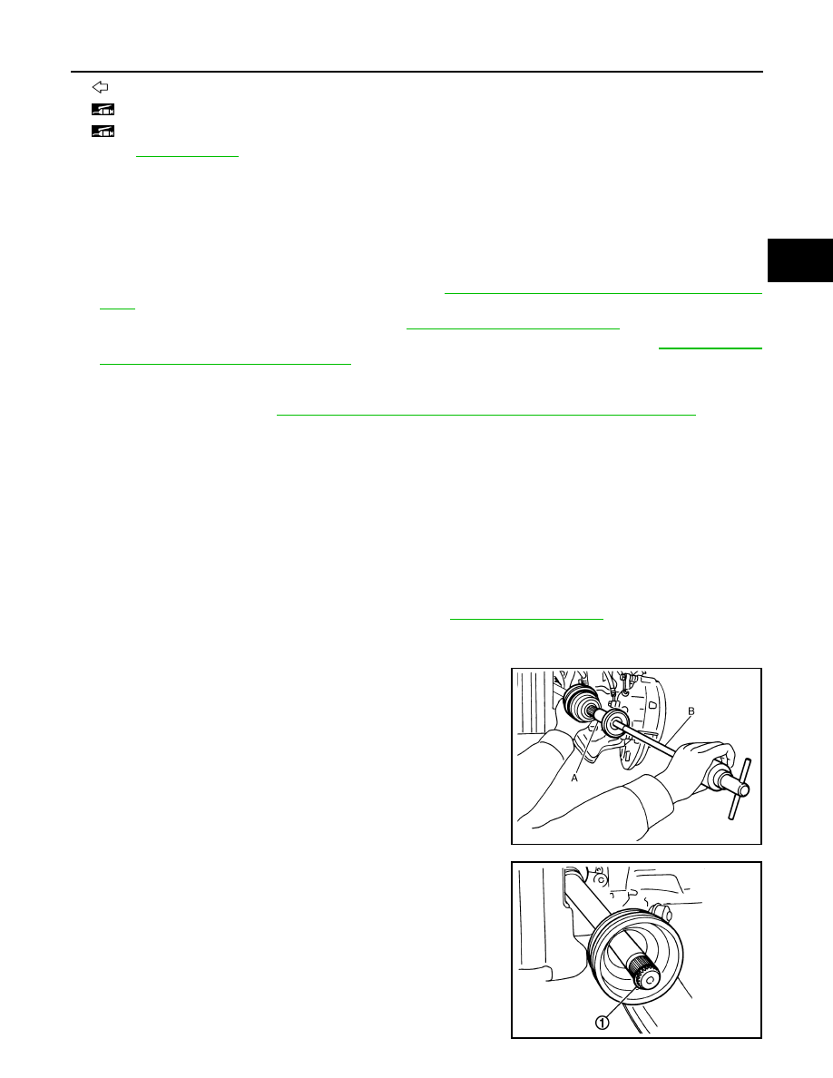
12. Screw drive shaft puller (A) into joint sub-assembly screw part to
a length of 30 mm (1.18 in) or more. Support drive shaft with one
hand and pull out joint sub-assembly with a sliding hammer (B)
from housing assembly.
CAUTION:
• Align a sliding hammer and drive shaft and remove them
by pulling firmly and uniformly.
• If joint sub-assembly cannot be pulled out, try after
removing drive shaft from vehicle.
13. Remove circular clip (1) from housing assembly.
14. Remove boot from housing assembly.
: Wheel side
1: Fill NISSAN Genuine grease or equivalent.
2: Apply paste [service parts (440037S000)].
Refer to
for symbols not described on the above.
JPDIF0022ZZ
JPDIF0007ZZ