Nissan Murano Z51. Manual - part 607


  Главная      Nissan     Nissan Murano Z51 (2010 year) - Service Manual


поиск по сайту            


содержание   ..  605  606  607  608   ..


Nissan Murano Z51. Manual - part 607


EC-436

< DTC/CIRCUIT DIAGNOSIS >

[VQ35DE]

ELECTRONIC CONTROLLED ENGINE MOUNT

Check the following.
• Harness connectors E6, F123
• 10 A fuse (No. 3)
• Fuse block (J/B) connector E103
• Harness for open or short between electronic controlled engine mount control solenoid valve and fuse

>> Repair open circuit, short to ground or short to power in harness or connectors.

5.

CHECK ELECTRONIC CONTROLLED ENGINE MOUNT CONTROL SOLENOID VALVE OUTPUT SIG-

NAL CIRCUIT FOR OPEN AND SHORT

1.

Disconnect ECM harness connector.

2.

Check the continuity between ECM harness connector and electronic controlled engine mount control
solenoid valve harness connector.

3.

Also check harness for short to ground and short to power.

Is the inspection result normal?

YES

>> GO TO 6.

NO

>> Repair open circuit, short to ground or short to power in harness connectors.

6.

CHECK ELECTRONIC CONTROLLED ENGINE MOUNT CONTROL SOLENOID VALVE

Refer to 

EC-436, "Component Inspection"

.

Is the inspection result normal?

YES

>> GO TO 7.

NO

>> Replace electronic controlled engine mount control solenoid valve.
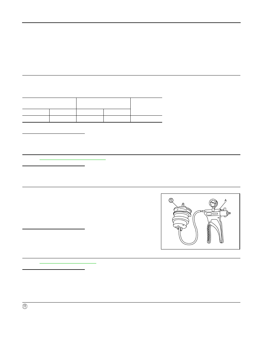
7.

CHECK ELECTRONIC CONTROLLED ENGINE MOUNT

1.

Turn ignition switch OFF.

2.

Install vacuum pump (A) to electronic controlled engine mount
(1).

3.

Check that a vacuum is maintained when applying the vacuum
of -40 kPa (-0.41 kg/cm

2

, -5.8 psi) to electronic controlled engine

mount.

4.

Also visually check electronic controlled engine mount.

Is the inspection result normal?

YES

>> GO TO 8.

NO

>> Replace electronic controlled engine mount.

8.

CHECK INTERMITTENT INCIDENT

Refer to 

GI-39, "Intermittent Incident"

.

Is the inspection result normal?

YES

>> Replace intake manifold collector.

NO

>> Repair or replace malfunctioning part.

Component Inspection

INFOID:0000000005536868

1.

CHECK ELECTRONIC CONTROLLED ENGINE MOUNT CONTROL SOLENOID VALVE

 With CONSULT-III

1.

Turn ignition switch OFF.

2.

Reconnect electronic controlled engine mount control solenoid valve harness connector.

3.

Disconnect vacuum hoses connected to electronic controlled engine mount control solenoid valve.

4.

Turn ignition switch ON.

ECM

Electronic controlled engine 

mount control solenoid valve

Continuity

Connector

Terminal

Connector

Terminal

F7

28

F11

2

Existed

MBIB1237E

ELECTRONIC CONTROLLED ENGINE MOUNT

EC-437

< DTC/CIRCUIT DIAGNOSIS >

[VQ35DE]

C

D

E

F

G

H

I

J

K

L

M

A

EC

N

P

O

5.

Select “ENGINE MOUNTING” in “ACTIVE TEST” mode with CONSULT-III.

6.

Check air passage continuity and operation delay time under the
following conditions.

 Without CONSULT-III

1.

Turn ignition switch OFF.

2.

Disconnect electronic controlled engine mount control solenoid
valve harness connector.

3.

Disconnect vacuum hoses connected to electronic controlled engine mount control solenoid valve.

4.

Check air passage continuity and operation delay time under the
following conditions.

Is the inspection result normal?

YES

>> INSPECTION END

NO

>> Replace electronic controlled engine mount control sole-

noid valve.

Condition

(ENGINE MOUNTING)

Air passage continuity 

between (A) and (B)

Air passage continuity 

between (A) and (C)

TRVL

Existed

Not existed

IDLE

Not existed

Existed

Condition

Air passage continuity 

between (A) and (B)

Air passage continuity 

between (A) and (C)

12 V direct current supply be-
tween terminals 1 and 2

Existed

Not existed

No supply

Not existed

Existed

JMBIA0180ZZ

PBIB2532E

EC-438

< DTC/CIRCUIT DIAGNOSIS >

[VQ35DE]

FUEL INJECTOR

FUEL INJECTOR

Description

INFOID:0000000005536869

The fuel injector is a small, precise solenoid valve. When the ECM
supplies a ground to the fuel injector circuit, the coil in the fuel injec-
tor is energized. The energized coil pulls the ball valve back and
allows fuel to flow through the fuel injector into the intake manifold.
The amount of fuel injected depends upon the injection pulse dura-
tion. Pulse duration is the length of time the fuel injector remains
open. The ECM controls the injection pulse duration based on
engine fuel needs.

Component Function Check

INFOID:0000000005536870

1.

INSPECTION START

Turn ignition switch to START.
Are any cylinders ignited?

YES

>> GO TO 2.

NO

>> Go to 

EC-438, "Diagnosis Procedure"

.

2.

CHECK FUEL INJECTOR FUNCTION

With CONSULT-III

1.

Start engine.

2.

Perform “POWER BALANCE” in “ACTIVE TEST” mode with CONSULT-III.

3.

Check that each circuit produces a momentary engine speed drop.

Without CONSULT-III

1.

Start engine.

2.

Listen to each fuel injector operating sound.

Is the inspection result normal?

YES

>> INSPECTION END

NO

>> Go to 

EC-438, "Diagnosis Procedure"

.

Diagnosis Procedure

INFOID:0000000005536871

1.

CHECK FUEL INJECTOR POWER SUPPLY CIRCUIT

1.

Turn ignition switch OFF.

2.

Disconnect fuel injector harness connector.

3.

Turn ignition switch ON.

4.

Check the voltage between fuel injector harness connector and ground.

PBIA9664J

Clicking sound should be heard.

PBIB3332E

FUEL INJECTOR

EC-439

< DTC/CIRCUIT DIAGNOSIS >

[VQ35DE]

C

D

E

F

G

H

I

J

K

L

M

A

EC

N

P

O

Is the inspection result normal?

YES

>> GO TO 3.

NO

>> GO TO 2.

2.

DETECT MALFUNCTIONING PART

Check the following.
• 10 A fuse (No.44)
• IPDM E/R harness connector F12
• Harness for open or short between fuel injector and IPDM E/R

>> Repair open circuit, short to ground or short to power in harness or connectors.

3.

CHECK FUEL INJECTOR OUTPUT SIGNAL CIRCUIT FOR OPEN AND SHORT

1.

Turn ignition switch OFF.

2.

Disconnect ECM harness connector.

3.

Check the continuity between fuel injector harness connector and ECM harness connector.

4.

Also check harness for short to ground and short to power.

Is the inspection result normal?

YES

>> GO TO 4.

NO

>> Repair open circuit, short to ground or short to power in harness or connectors.

4.

CHECK FUEL INJECTOR

Refer to 

EC-440, "Component Inspection"

.

Is the inspection result normal?

YES

>> GO TO 5.

NO

>> Replace malfunctioning fuel injector.

5.

CHECK INTERMITTENT INCIDENT

Refer to 

GI-39, "Intermittent Incident"

.

Is the inspection result normal?

YES

>> Replace IPDM E/R.

NO

>> INSPECTION END

Fuel injector

Ground

Voltage

Cylinder

Connector

Terminal

1

F37

1

Ground

Battery voltage

2

F38

1

3

F39

1

4

F40

1

5

F41

1

6

F42

1

Fuel injector

ECM

Continuity

Cylinder

Connector

Terminal

Connector

Terminal

1

F37

2

F7

32

Existed

2

F38

2

31

3

F39

2

30

4

F40

2

29

5

F41

2

3

6

F42

2

1


содержание   ..  605  606  607  608   ..