содержание .. 603 604 605 606 ..
Nissan Murano Z51. Manual - part 605
EC-428
< DTC/CIRCUIT DIAGNOSIS >
[VQ35DE]
COOLING FAN
COOLING FAN
Description
INFOID:0000000005536857
The ECM controls the cooling fan corresponding to the vehicle speed, engine coolant temperature, refrigerant
pressure, and air conditioner ON signal. The control system has 4-step control [HIGH/MIDDLE/LOW/OFF].
COOLING FAN MOTOR
The cooling fan operates at each speed when the current flows in the cooling fan motor as per the following.
The cooling fan operates at low (LOW) speed when cooling fan motors-1 and -2 are circuited in series under
the middle speed condition.
Refer to
Component Function Check
INFOID:0000000005536858
1.
CHECK COOLING FAN FUNCTION
With CONSULT-III
1.
Turn ignition switch ON.
2.
Perform “COOLING FAN” in “ACTIVE TEST” mode with CONSULT-III.
3.
Check that cooling fan operates at each speed.
Without CONSULT-III
1.
Perform IPDM E/R auto active test and check cooling fan motors operation, refer to
.
2.
Check that cooling fan operates at each speed.
Is the inspection result normal?
YES
>> INSPECTION END
NO
>> Go to
Diagnosis Procedure
INFOID:0000000005536859
1.
CHECK COOLING FAN RELAY POWER SUPPLY CIRCUIT
1.
Turn ignition switch OFF.
2.
Disconnect cooling fan relays-2, -3.
3.
Turn ignition switch ON.
4.
Check the voltage between cooling fan relays-2, -3 harness connectors and ground.
Is the inspection result normal?
YES
>> GO TO 3.
NO
>> GO TO 2.
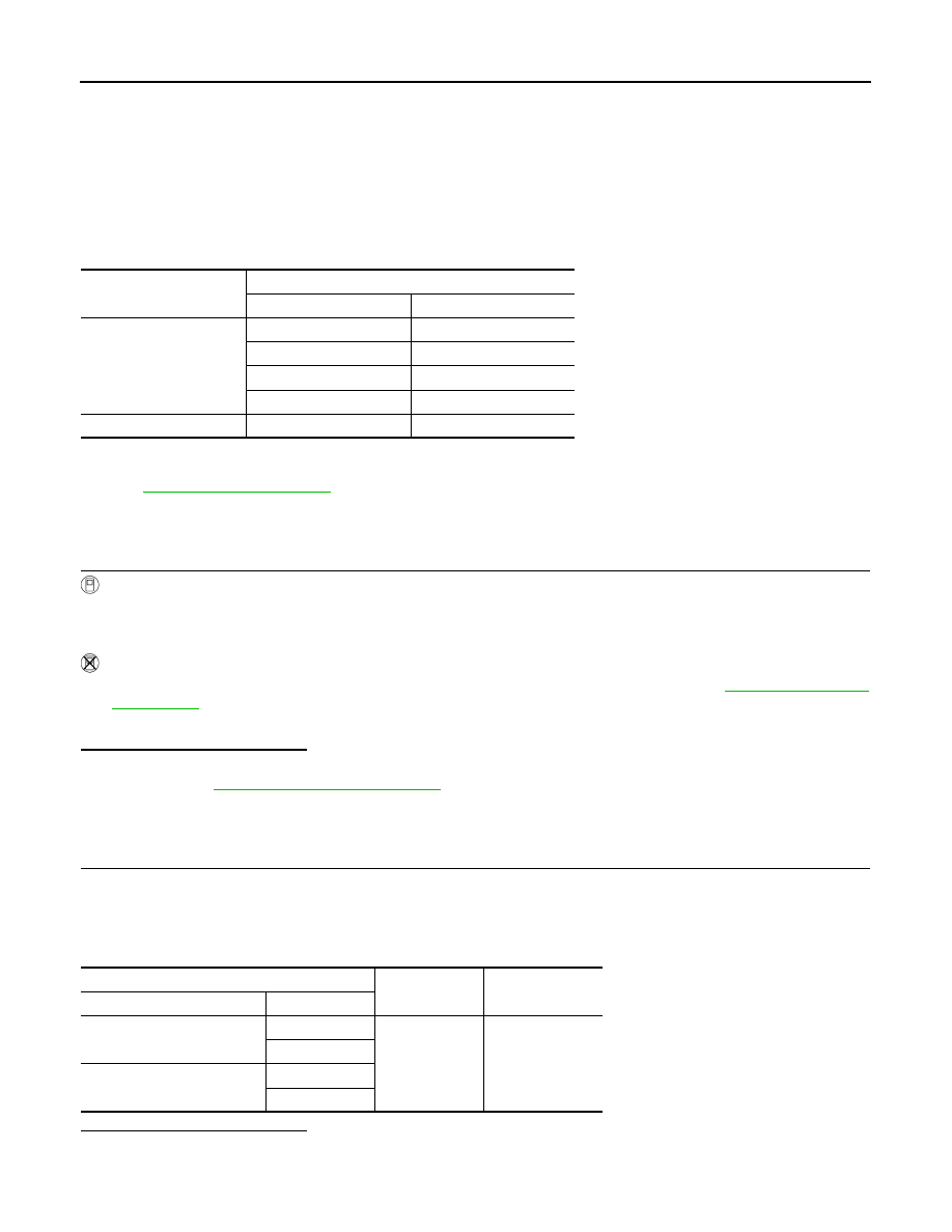
Cooling fan speed
Cooling fan motor terminals
(+)
(–)
Middle (MID)
1
3 and 4
2
3 and 4
1 and 2
3
1 and 2
4
High (HI)
1 and 2
3 and 4
Cooling fan relay
Ground
Voltage
Connector
Terminal
E57
(cooling fan relay-2)
2
Ground
Battery voltage
5
E59
(cooling fan relay-3)
2
5