содержание .. 606 607 608 609 ..
Nissan Murano Z51. Manual - part 608
EC-440
< DTC/CIRCUIT DIAGNOSIS >
[VQ35DE]
FUEL INJECTOR
Component Inspection
INFOID:0000000005536872
1.
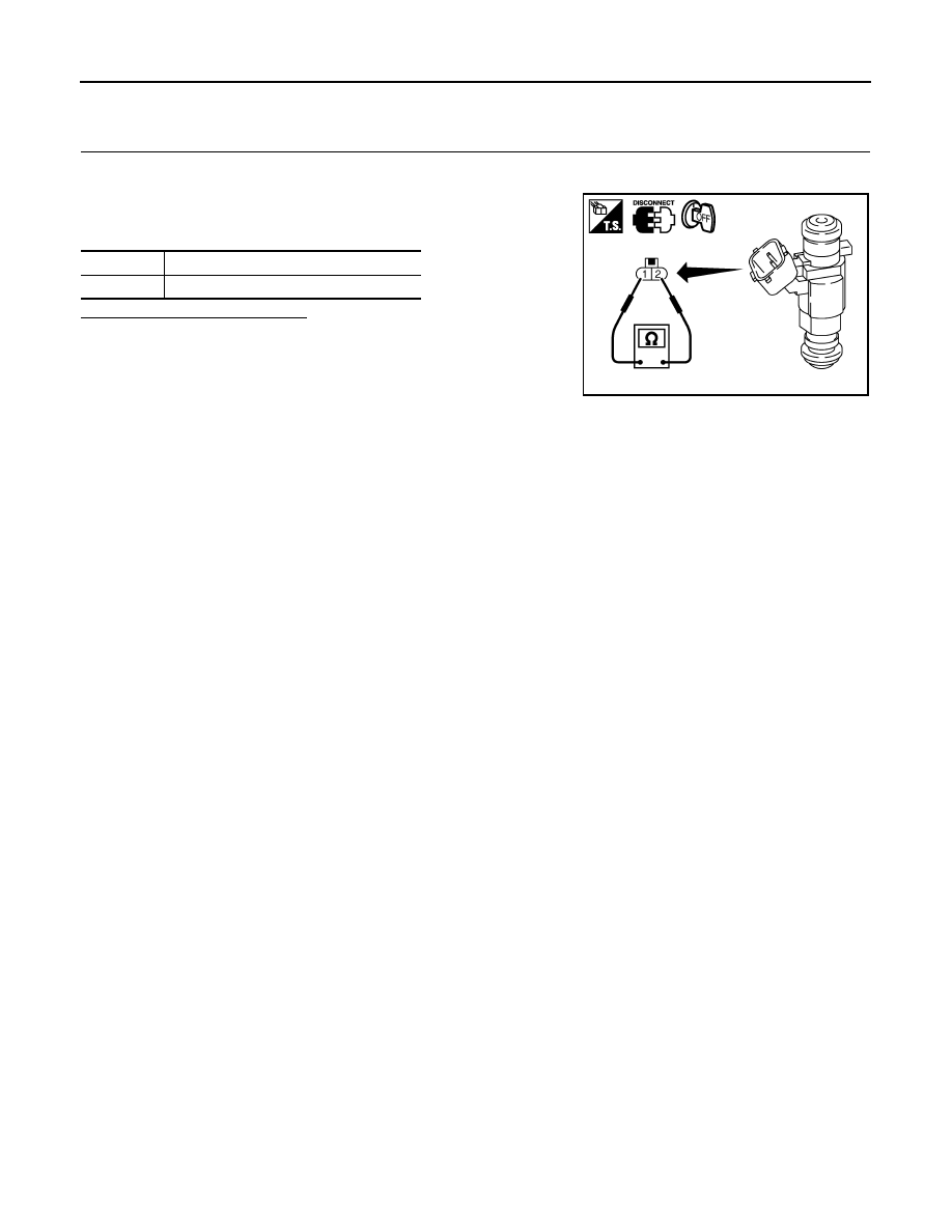
CHECK FUEL INJECTOR
1.
Turn ignition switch OFF.
2.
Disconnect fuel injector harness connector.
3.
Check resistance between fuel injector terminals as per the fol-
lowing.
Is the inspection result normal?
YES
>> INSPECTION END
NO
>> Replace malfunctioning fuel injector.
Terminals
Resistance
1 and 2
11.1 - 14.5
Ω
[at 10 - 60
°
C (50 - 140
°
F)]
PBIB1727E