Nissan Murano Z51. Manual - part 527


  Главная      Nissan     Nissan Murano Z51 (2010 year) - Service Manual


поиск по сайту            


содержание   ..  525  526  527  528   ..


Nissan Murano Z51. Manual - part 527


EC-116

< SYSTEM DESCRIPTION >

[VQ35DE]

ON BOARD DIAGNOSTIC (OBD) SYSTEM

Explanation for Driving Patterns Except for “Misfire <Exhaust Quality Deterioration>”, “Fuel Injection System”
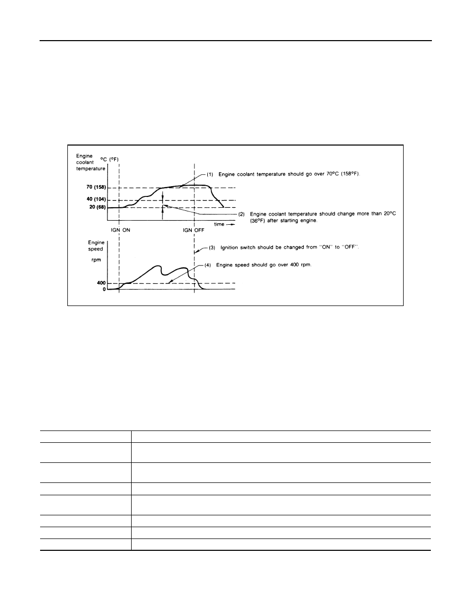
<Driving Pattern A>

• The A counter will be cleared when the malfunction is detected regardless of (1) - (4).
• The A counter will be counted up when (1) - (4) are satisfied without the same malfunction.
• The DTC will not be displayed after the A counter reaches 40.
<Driving Pattern B>
Driving pattern B means operating vehicle as per the following:
All components and systems should be monitored at least once by the OBD system.
• The B counter will be cleared when the malfunction is detected once regardless of the driving pattern.
• The B counter will be counted up when driving pattern B is satisfied without any malfunctions.
• The MIL will turn off when the B counter reaches 3 (*2 in OBD SYSTEM OPERATION CHART).

CONSULT-III Function

INFOID:0000000005536527

FUNCTION

*: The following emission-related diagnostic information is cleared when the ECM memory is erased.

• Diagnostic trouble codes

• 1st trip diagnostic trouble codes

• Freeze frame data

*4: The DTC and the freeze frame data 

will not be displayed any longer after 
vehicle is driven 40 times (pattern A) 
without the same malfunction.
(The DTC and the freeze frame data 
still remain in ECM.)

*5: When a malfunction is detected for 

the 1st time, the 1st trip DTC and the 
1st trip freeze frame data will be 
stored in ECM.

*6: 1st trip DTC will be cleared after vehi-

cle is driven once (pattern B) without 
the same malfunction.

*7: When the same malfunction is de-

tected in the 2nd trip, the 1st trip 
freeze frame data will be cleared.

JMBIA1920GB

Diagnostic test mode

Function

Work Support

This mode enables a technician to adjust some devices faster and more accurately by following the in-
dications on the CONSULT-III unit.

Self Diagnostic Result

Self-diagnostic results such as 1st trip DTC, DTCs and 1st trip freeze frame data or freeze frame data 
can be read and erased quickly.*

Data Monitor

Input/Output data in the ECM can be read.

Active Test

Diagnostic Test Mode in which CONSULT-III drives some actuators apart from the ECM and also shifts 
some parameters in a specified range.

DTC & SRT Confirmation

The status of system monitoring tests and the self-diagnosis status/results can be confirmed.

Function Test

This mode is used to inform customers when the vehicle requires periodic maintenance.

ECU Part Number

ECM part number can be read.

ON BOARD DIAGNOSTIC (OBD) SYSTEM

EC-117

< SYSTEM DESCRIPTION >

[VQ35DE]

C

D

E

F

G

H

I

J

K

L

M

A

EC

N

P

O

• 1st trip freeze frame data

• System readiness test (SRT) codes

• Test  values

WORK SUPPORT MODE

Work Item

*: This function is not necessary in the usual service procedure.

SELF-DIAG RESULTS MODE

Self Diagnostic Item

Regarding items of DTC and 1st trip DTC, refer to 

EC-498, "DTC Index"

.

Freeze Frame Data and 1st Trip Freeze Frame Data

WORK ITEM

CONDITION

USAGE

FUEL PRESSURE RELEASE

• FUEL PUMP WILL STOP BY TOUCHING “START” DUR-

ING IDLING.
CRANK A FEW TIMES AFTER ENGINE STALLS.

When releasing fuel pressure from 
fuel line

IDLE AIR VOL LEARN

• THE IDLE AIR VOLUME THAT KEEPS THE ENGINE 

WITHIN THE SPECIFIED RANGE IS MEMORIZED IN 
ECM.

When learning the idle air volume

SELF-LEARNING CONT

• THE COEFFICIENT OF SELF-LEARNING CONTROL 

MIXTURE RATIO RETURNS TO THE ORIGINAL COEF-
FICIENT.

When clearing mixture ratio self-
learning value

EVAP SYSTEM CLOSE

CLOSE THE EVAP CANISTER VENT CONTROL VALVE IN 
ORDER TO MAKE EVAP SYSTEM CLOSE UNDER THE 
FOLLOWING CONDITIONS.
• IGN  SW  ON
• ENGINE NOT RUNNING
• AMBIENT TEMPERATURE IS ABOVE 0

°

C (32

°

F).

• NO VACUUM AND NO HIGH PRESSURE IN EVAP SYS-

TEM

• FUEL TANK TEMP. IS MORE THAN 0

°

C (32

°

F).

• WITHIN 10 MINUTES AFTER STARTING “EVAP SYS-

TEM CLOSE”

• WHEN TRYING TO EXECUTE “EVAP SYSTEM CLOSE” 

UNDER THE CONDITION EXCEPT ABOVE, CONSULT-
III WILL DISCONTINUE IT AND DISPLAY APPROPRI-
ATE INSTRUCTION.
NOTE:
WHEN STARTING ENGINE, CONSULT-III MAY DIS-
PLAY “BATTERY VOLTAGE IS LOW. CHARGE BAT-
TERY”, EVEN WHEN USING A CHARGED BATTERY.

When detecting EVAP vapor leak-
age in the EVAP system

VIN REGISTRATION

• IN THIS MODE, VIN IS REGISTERED IN ECM.

When registering VIN in ECM

TARGET IDLE RPM ADJ*

• IDLE CONDITION

When setting target idle speed

TARGET IGN TIM ADJ*

• IDLE CONDITION

When adjusting target ignition tim-
ing

Freeze frame data item*

Description

DIAG TROUBLE CODE
[PXXXX]

• The engine control component part/control system has a trouble code that is displayed as PXXXX. (Refer 

to 

EC-498, "DTC Index"

.)

FUEL SYS-B1

• “Fuel injection system status” at the moment a malfunction is detected is displayed.
• One of the following mode is displayed.

Mode2: Open loop due to detected system malfunction
Mode3: Open loop due to driving conditions (power enrichment, deceleration enleanment)
Mode4: Closed loop - using oxygen sensor(s) as feedback for fuel control
Mode5: Open loop - has not yet satisfied condition to go to closed loop

FUEL SYS-B2

CAL/LD VALUE [%]

• The calculated load value at the moment a malfunction is detected is displayed.

EC-118

< SYSTEM DESCRIPTION >

[VQ35DE]

ON BOARD DIAGNOSTIC (OBD) SYSTEM

*: The items are the same as those of 1st trip freeze frame data.

DATA MONITOR MODE

Monitored Item

×

: Applicable

COOLANT TEMP [

°

C] or 

[

°

F]

• The engine coolant temperature at the moment a malfunction is detected is displayed.

L-FUEL TRM-B1 [%]

• “Long-term fuel trim” at the moment a malfunction is detected is displayed.
• The long-term fuel trim indicates much more gradual feedback compensation to the base fuel schedule 

than short-term fuel trim.

L-FUEL TRM-B2 [%]

S-FUEL TRM-B1 [%]

• “Short-term fuel trim” at the moment a malfunction is detected is displayed.
• The short-term fuel trim indicates dynamic or instantaneous feedback compensation to the base fuel 

schedule.

S-FUEL TRM-B2 [%]

ENGINE SPEED [rpm]

• The engine speed at the moment a malfunction is detected is displayed.

VEHICL SPEED
[km/h] or [mph]

• The vehicle speed at the moment a malfunction is detected is displayed.

ABSOL TH·P/S [%]

• The throttle valve opening angle at the moment a malfunction is detected is displayed.

B/FUEL SCHDL [msec]

• The base fuel schedule at the moment a malfunction is detected is displayed.

INT/A TEMP SE [

°

C] or 

[

°

F]

• The intake air temperature at the moment a malfunction is detected is displayed.

INT MANI PRES [kPa] 

• These items are displayed but are not applicable to this model.

COMBUST CONDITION

Freeze frame data item*

Description

Monitored item

Unit

Description

Remarks

ENG SPEED

rpm

• Indicates the engine speed computed from the 

signal of the crankshaft position sensor (POS) 
and camshaft position sensor (PHASE).

• Accuracy becomes poor if engine 

speed drops below the idle rpm.

• If the signal is interrupted while the 

engine is running, an abnormal value 
may be indicated.

MAS A/F SE-B1

V

• The signal voltage of the mass air flow sensor is 

displayed.

• When the engine is stopped, a certain 

value is indicated.

• When engine is running, specification 

range is indicated in “SPEC”.

B/FUEL SCHDL

msec

• “Base fuel schedule” indicates the fuel injection 

pulse width programmed into ECM, prior to any 
learned on board correction.

• When engine is running, specification 

range is indicated in “SPEC”.

A/F ALPHA-B1

%

• The mean value of the air-fuel ratio feedback cor-

rection factor per cycle is indicated.

• When the engine is stopped, a certain 

value is indicated.

• This data also includes the data for 

the air-fuel ratio learning control.

• When engine is running, specification 

range is indicated in “SPEC”.

A/F ALPHA-B2

COOLAN TEMP/S

°

C or 

°

F

• The engine coolant temperature (determined by 

the signal voltage of the engine coolant tempera-
ture sensor) is displayed.

• When the engine coolant temperature 

sensor is open or short-circuited, 
ECM enters fail-safe mode. The en-
gine coolant temperature determined 
by the ECM is displayed.

A/F SEN1 (B1)

V

• The A/F signal computed from the input signal of 

the air fuel ratio (A/F) sensor 1 is displayed.

A/F SEN1 (B2)

HO2S2 (B1)

V

• The signal voltage of the heated oxygen sensor 2 

is displayed.

HO2S2 (B2)

HO2S2 MNTR(B1)

RICH/LEAN

• Display of heated oxygen sensor 2 signal:

RICH: means the amount of oxygen after three 
way catalyst is relatively small.
LEAN: means the amount of oxygen after three 
way catalyst is relatively large.

• When the engine is stopped, a certain 

value is indicated.

HO2S2 MNTR(B2)

ON BOARD DIAGNOSTIC (OBD) SYSTEM

EC-119

< SYSTEM DESCRIPTION >

[VQ35DE]

C

D

E

F

G

H

I

J

K

L

M

A

EC

N

P

O

VHCL SPEED SE

km/h or mph

• The vehicle speed computed from the vehicle 

speed signal sent from combination meter is dis-
played.

BATTERY VOLT

V

• The power supply voltage of ECM is displayed.

ACCEL SEN 1

V

• The accelerator pedal position sensor signal volt-

age is displayed.

• ACCEL SEN 2 signal is converted by 

ECM internally. Thus, it differs from 
ECM terminal voltage signal.

ACCEL SEN 2

TP SEN 1-B1

V

• The throttle position sensor signal voltage is dis-

played.

• TP SEN 2-B1 signal is converted by 

ECM internally. Thus, it differs from 
ECM terminal voltage signal.

TP SEN 2-B1

FUEL T/TMP SE

°

C or 

°

F

• The fuel temperature (determined by the signal 

voltage of the fuel tank temperature sensor) is 
displayed.

INT/A TEMP SE

°

C or 

°

F

• The intake air temperature (determined by the 

signal voltage of the intake air temperature sen-
sor) is indicated.

EVAP SYS PRES

V

• The signal voltage of EVAP control system pres-

sure sensor is displayed.

FUEL LEVEL SE

V

• The signal voltage of the fuel level sensor is dis-

played.

START SIGNAL

ON/OFF

• Indicates start signal status [ON/OFF] computed 

by the ECM according to the signals of engine 
speed and battery voltage.

• After starting the engine, [OFF] is dis-

played regardless of the starter sig-
nal.

CLSD THL POS

ON/OFF

• Indicates idle position [ON/OFF] computed by 

ECM according to the accelerator pedal position 
sensor signal.

AIR COND SIG

ON/OFF

• Indicates [ON/OFF] condition of the air condition-

er switch as determined by the air conditioner sig-
nal.

P/N POSI SW

ON/OFF

• Indicates [ON/OFF] condition from the park/neu-

tral position (PNP) signal.

PW/ST SIGNAL

ON/OFF

• [ON/OFF] condition of the power steering system 

(determined by the signal voltage of the power 
steering pressure sensor) is indicated.

LOAD SIGNAL

ON/OFF

• Indicates [ON/OFF] condition from the electrical 

load signal.
ON: Rear window defogger switch is ON and/or 
lighting switch is in 2nd position.
OFF: Both rear window defogger switch and light-
ing switch are OFF.

IGNITION SW

ON/OFF

• Indicates [ON/OFF] condition from ignition switch 

signal.

HEATER FAN SW

ON/OFF

• Indicates [ON/OFF] condition from the heater fan 

switch signal.

BRAKE SW

ON/OFF

• Indicates [ON/OFF] condition from the stop lamp 

switch signal.

INJ PULSE-B1

msec

• Indicates the actual fuel injection pulse width 

compensated by ECM according to the input sig-
nals.

• When the engine is stopped, a certain 

computed value is indicated.

INJ PULSE-B2

IGN TIMING

BTDC

• Indicates the ignition timing computed by ECM 

according to the input signals.

• When the engine is stopped, a certain 

value is indicated.

CAL/LD VALUE

%

• “Calculated load value” indicates the value of the 

current air flow divided by peak air flow.

MASS AIRFLOW

g·m/s

• Indicates the mass air flow computed by ECM ac-

cording to the signal voltage of the mass air flow 
sensor.

Monitored item

Unit

Description

Remarks


содержание   ..  525  526  527  528   ..