Nissan Murano Z51. Manual - part 526


  Главная      Nissan     Nissan Murano Z51 (2010 year) - Service Manual


поиск по сайту            


содержание   ..  524  525  526  527   ..


Nissan Murano Z51. Manual - part 526


EC-112

< SYSTEM DESCRIPTION >

[VQ35DE]

ON BOARD DIAGNOSTIC (OBD) SYSTEM

• It is impossible to switch the diagnostic mode when an accelerator pedal position sensor circuit has

a malfunction.

• ECM always returns to Diagnostic Test Mode I after the ignition switch is turned OFF.
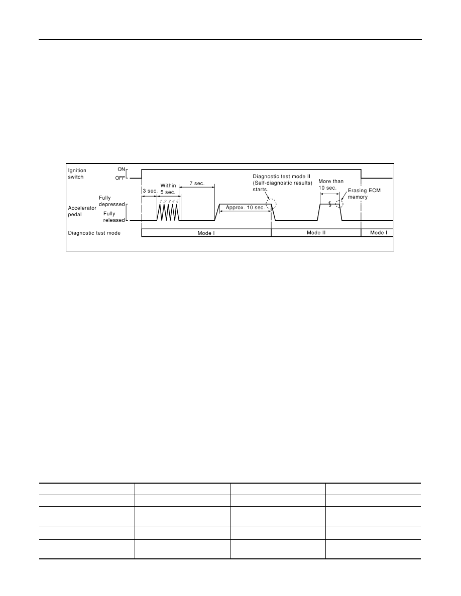
HOW TO SET DIAGNOSTIC TEST MODE II (SELF-DIAGNOSTIC RESULTS)
1.

Confirm that accelerator pedal is fully released, turn ignition switch ON and wait 3 seconds.

2.

Repeat the following procedure quickly 5 times within 5 seconds.

-

Fully depress the accelerator pedal.

-

Fully release the accelerator pedal.

3.

Wait 7 seconds, fully depress the accelerator pedal and keep it depressed for approx. 10 seconds until the
MIL starts blinking.

4.

Fully release the accelerator pedal.
ECM has entered to Diagnostic Test Mode II (Self-diagnostic results).
NOTE:
Wait until the same DTC (or 1st trip DTC) appears to completely confirm all DTCs.

HOW TO ERASE DIAGNOSTIC TEST MODE II (SELF-DIAGNOSTIC RESULTS)
1.

Set ECM in Diagnostic Test Mode II (Self-diagnostic results). Refer to “How to Set Diagnostic Test Mode II
(Self-diagnostic Results)”.

2.

Fully depress the accelerator pedal and keep it depressed for more than 10 seconds.
The emission-related diagnostic information has been erased from the backup memory in the ECM.

3.

Fully release the accelerator pedal, and confirm the DTC 0000 is displayed.

• If the battery is disconnected, the DTC will be lost from the backup memory within 24 hours.
• Do not erase the stored memory before starting trouble diagnoses.

OBD System Operation Chart

Relationship Between MIL, 1st Trip DTC, DTC, and Detectable Items

• When a malfunction is detected for the 1st time, the 1st trip DTC and the 1st trip freeze frame data are

stored in the ECM memory.

• When the same malfunction is detected in two consecutive trips, the DTC and the freeze frame data are

stored in the ECM memory, and the MIL will come on.

• The MIL will turn off after the vehicle is driven 3 times (driving pattern B) with no malfunction. A drive is

counted only when the recorded driving pattern is met (as stored in the ECM). If another malfunction occurs
while counting, the counter will reset.

• The DTC and the freeze frame data will be stored until the vehicle is driven 40 times (driving pattern A) with-

out the same malfunction recurring (except for Misfire and Fuel Injection System). For Misfire and Fuel Injec-
tion System, the DTC and freeze frame data will be stored until the vehicle is driven 80 times (driving pattern
C) without the same malfunction recurring. The “TIME” in “SELF-DIAGNOSTIC RESULTS” mode of CON-
SULT-III will count the number of times the vehicle is driven.

• The 1st trip DTC is not displayed when the self-diagnosis results in OK for the 2nd trip.

Summary Chart

PBIB0092E

Items

Fuel Injection System

Misfire

Other

MIL (turns off)

3 (pattern B)

3 (pattern B)

3 (pattern B)

DTC, Freeze Frame Data (no 
display)

80 (pattern C)

80 (pattern C)

40 (pattern A)

1st Trip DTC (clear)

1 (pattern C), *

1

1 (pattern C), *

1

1 (pattern B)

1st Trip Freeze Frame Data 
(clear)

*1, *2

*1, *2

1 (pattern B)

ON BOARD DIAGNOSTIC (OBD) SYSTEM

EC-113

< SYSTEM DESCRIPTION >

[VQ35DE]

C

D

E

F

G

H

I

J

K

L

M

A

EC

N

P

O

For details about patterns B and C under “Fuel Injection System” and “Misfire”, see “EXPLANATION FOR DRIVING PATTERNS FOR
“MISFIRE <EXHAUST QUALITY DETERIORATION>”, “FUEL INJECTION SYSTEM”.

For details about patterns A and B under Other, see “EXPLANATION FOR DRIVING PATTERNS FOR “MISFIRE <EXHAUST QUALITY
DETERIORATION>”, “FUEL INJECTION SYSTEM”.

*1: Clear timing is at the moment OK is detected.

*2: Clear timing is when the same malfunction is detected in the 2nd trip.

Relationship Between MIL, DTC, 1st Trip DTC and Driving Patterns for “Misfire <Exhaust Quality Deterioration>”,
“Fuel Injection System”

*1: When the same malfunction is de-

tected in two consecutive trips, MIL 
will illuminate.

*2: MIL will turn off after vehicle is driven 

3 times (pattern B) without any mal-
functions.

*3: When the same malfunction is de-

tected in two consecutive trips, the 
DTC and the freeze frame data will be 
stored in ECM.

JMBIA1417GB

EC-114

< SYSTEM DESCRIPTION >

[VQ35DE]

ON BOARD DIAGNOSTIC (OBD) SYSTEM

Explanation for Driving Patterns for “Misfire <Exhaust Quality Deterioration>”, “Fuel Injection System”

<Driving Pattern B>
Driving pattern B means the vehicle operation as per the following:
All components and systems should be monitored at least once by the OBD system.
• The B counter will be cleared when the malfunction is detected once regardless of the driving pattern.
• The B counter will be counted up when driving pattern B is satisfied without any malfunction.
• The MIL will turn off when the B counter reaches 3. (*2 in “OBD SYSTEM OPERATION CHART”)
<Driving Pattern C>
Driving pattern C means operating vehicle as per the following:
The following conditions should be satisfied at the same time:
Engine speed: (Engine speed in the freeze frame data) 

±

 375 rpm

Calculated load value: (Calculated load value in the freeze frame data) x (1 

±

 0.1) [%]

Engine coolant temperature (T) condition:
• When the freeze frame data shows lower than 70

°

C (158

°

F), T should be lower than 70

°

C (158

°

F).

• When the freeze frame data shows higher than or equal to 70

°

C (158

°

F), T should be higher than or equal to

70

°

C (158

°

F).

Example:
If the stored freeze frame data is as per the following:
Engine speed: 850 rpm, Calculated load value: 30%, Engine coolant temperature: 80

°

C (176

°

F)

To be satisfied with driving pattern C, the vehicle should run under the following conditions:
Engine speed: 475 - 1,225 rpm, Calculated load value: 27 - 33%, Engine coolant temperature: more than 70

°

C

(158

°

F)

• The C counter will be cleared when the malfunction is detected regardless of vehicle conditions above.
• The C counter will be counted up when vehicle conditions above are satisfied without the same malfunction.
• The DTC will not be displayed after C counter reaches 80.
• The 1st trip DTC will be cleared when C counter is counted once without the same malfunction after DTC is

stored in ECM.

Relationship Between MIL, DTC, 1st Trip DTC and Driving Patterns Except For “Misfire <Exhaust Quality Deteriora-
tion>”, “Fuel Injection System”

*4: The DTC and the freeze frame data 

will not be displayed any longer after 
vehicle is driven 80 times (pattern C) 
without the same malfunction. (The 
DTC and the freeze frame data still 
remain in ECM.)

*5: When a malfunction is detected for 

the 1st time, the 1st trip DTC and the 
1st trip freeze frame data will be 
stored in ECM.

*6: The 1st trip DTC and the 1st trip 

freeze frame data will be cleared at 
the moment OK is detected.

*7: When the same malfunction is de-

tected in the 2nd trip, the 1st trip 
freeze frame data will be cleared.

*8: 1st trip DTC will be cleared when ve-

hicle is driven once (pattern C) with-
out the same malfunction after DTC 
is stored in ECM.

ON BOARD DIAGNOSTIC (OBD) SYSTEM

EC-115

< SYSTEM DESCRIPTION >

[VQ35DE]

C

D

E

F

G

H

I

J

K

L

M

A

EC

N

P

O

*1: When the same malfunction is de-

tected in two consecutive trips, MIL 
will illuminate.

*2: MIL will turn off after vehicle is driven 

3 times (pattern B) without any mal-
functions.

*3: When the same malfunction is de-

tected in two consecutive trips, the 
DTC and the freeze frame data will be 
stored in ECM.

JMBIA1418GB


содержание   ..  524  525  526  527   ..