Nissan Murano Z51. Manual - part 498


  Главная      Nissan     Nissan Murano Z51 (2010 year) - Service Manual


поиск по сайту            


содержание   ..  496  497  498  499   ..


Nissan Murano Z51. Manual - part 498


DLN-126

< SERVICE DATA AND SPECIFICATIONS (SDS) 

[REAR FINAL DRIVE: R145]

SERVICE DATA AND SPECIFICATIONS (SDS)

SERVICE DATA AND SPECIFICATIONS (SDS)

SERVICE DATA AND SPECIFICATIONS (SDS)

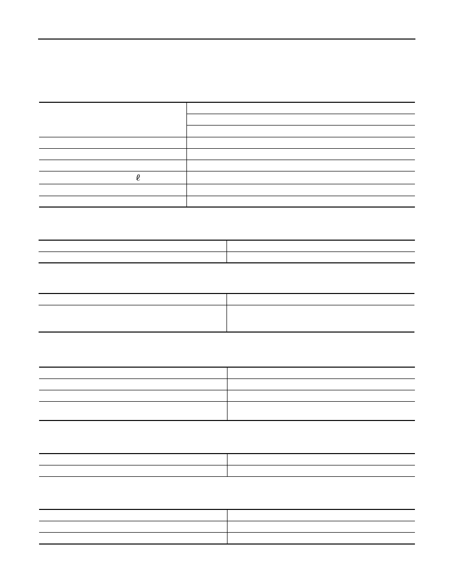
General Specification

INFOID:0000000005514274

Drive Gear Runout

INFOID:0000000005514275

Unit: mm (in)

Differential Side Gear Clearance

INFOID:0000000005514276

Unit: mm (in)

Preload Torque

INFOID:0000000005514277

Unit: N·m (kg-m, in-lb)

Backlash

INFOID:0000000005514278

Unit: mm (in)

Companion Flange Runout

INFOID:0000000005514279

Unit: mm (in)

Applied model

AWD

VQ35DE

CVT

Final drive model

R145

Gear ratio

2.466

Number of teeth (Drive gear/Drive pinion)

37/15

Oil capacity (Approx.)

 (US pt, lmp pt)

0.55 (1-1/8, 1)

Number of pinion gears

2

Drive pinion adjustment spacer type

Collapsible

Item

Limit

Drive gear back face runout

0.05 (0.0020)

Item

Standard

Side gear backlash (Clearance between side gear and differential 
case)

0.2 (0.008) or less

(Each gear should rotate smoothly without excessive resistance 

during differential motion.)

Item

Standard

Pinion bearing (P

1

)

0.69 – 1.18 (0.07 – 0.12, 7 – 10)

Side bearing (P

2

)

0.64 – 0.98 (0.07 – 0.09, 6 – 8)

Side bearing to pinion bearing (Total preload)
(Total preload = P

1

 + P

2

)

1.33 – 2.16 (0.14 – 0.22, 12 – 19)

Item

Standard

Drive gear to drive pinion gear

0.10 – 0.15 (0.0039 – 0.0059)

Item

Limit

Companion flange face

0.13 (0.0051)

Inner side of the companion flange

0.19 (0.0075)

EC-1

ENGINE

C

D

E

F

G

H

I

J

K

L

M

SECTION 

EC

A

EC

N

O

P

CONTENTS

ENGINE CONTROL SYSTEM

VQ35DE

BASIC INSPECTION  ....................................

8

DIAGNOSIS AND REPAIR WORKFLOW  ..........

8

Work Flow  .................................................................

8

Diagnostic Work Sheet ............................................

11

INSPECTION AND ADJUSTMENT ....................

13

BASIC INSPECTION  .................................................

13

BASIC INSPECTION : Special Repair Require-
ment ........................................................................

13

ADDITIONAL SERVICE WHEN REPLACING 
CONTROL UNIT  ........................................................

16

ADDITIONAL SERVICE WHEN REPLACING 
CONTROL UNIT : Description  ................................

16

ADDITIONAL SERVICE WHEN REPLACING 
CONTROL UNIT : Special Repair Requirement  .....

16

IDLE SPEED  ..............................................................

16

IDLE SPEED : Description  ......................................

16

IDLE SPEED : Special Repair Requirement  ...........

16

IGNITION TIMING ......................................................

17

IGNITION TIMING : Description ..............................

17

IGNITION TIMING : Special Repair Requirement 

....

17

VIN REGISTRATION  .................................................

17

VIN REGISTRATION : Description  .........................

17

VIN REGISTRATION : Special Repair Require-
ment ........................................................................

17

ACCELERATOR PEDAL RELEASED POSITION 
LEARNING ................................................................

18

ACCELERATOR PEDAL RELEASED POSITION 
LEARNING : Description .........................................

18

ACCELERATOR PEDAL RELEASED POSITION 
LEARNING : Special Repair Requirement  ..............

18

THROTTLE VALVE CLOSED POSITION LEARN-
ING .............................................................................

18

THROTTLE VALVE CLOSED POSITION 
LEARNING : Description  .........................................

18

THROTTLE VALVE CLOSED POSITION 
LEARNING : Special Repair Requirement  ..............

18

IDLE AIR VOLUME LEARNING  ................................

18

IDLE AIR VOLUME LEARNING : Description  .........

18

IDLE AIR VOLUME LEARNING : Special Repair 
Requirement ............................................................

18

MIXTURE RATIO SELF-LEARNING VALUE 
CLEAR .......................................................................

20

MIXTURE RATIO SELF-LEARNING VALUE 
CLEAR : Description ................................................

20

MIXTURE RATIO SELF-LEARNING VALUE 
CLEAR : Special Repair Requirement .....................

20

SYSTEM DESCRIPTION  .............................

21

ENGINE CONTROL SYSTEM  ..........................

21

System Diagram .....................................................

21

System Description ..................................................

22

Component Parts Location ....................................

22

Component Description  ...........................................

27

MULTIPORT FUEL INJECTION SYSTEM  .......

29

System Diagram .....................................................

29

System Description ..................................................

29

Component Parts Location ....................................

32

Component Description  ...........................................

37

ELECTRIC IGNITION SYSTEM  ........................

38

System Diagram .....................................................

38

System Description ..................................................

38

Component Parts Location ....................................

39

Component Description  ...........................................

44

AIR CONDITIONING CUT CONTROL  ..............

45

System Diagram  ......................................................

45

System Description ..................................................

45

Component Parts Location ....................................

46

Component Description  ...........................................

51

EC-2

AUTOMATIC SPEED CONTROL DEVICE 
(ASCD) ...............................................................

52

System Diagram  .....................................................

52

System Description .................................................

52

Component Parts Location ...................................

53

Component Description .........................................

58

CAN COMMUNICATION  ...................................

59

System Description .................................................

59

COOLING FAN CONTROL  ...............................

60

System Diagram  .....................................................

60

System Description .................................................

60

Component Parts Location ...................................

62

Component Description  ..........................................

67

ELECTRONIC CONTROLLED ENGINE 
MOUNT ..............................................................

68

System Diagram  .....................................................

68

System Description .................................................

68

Component Parts Location ...................................

71

Component Description .........................................

76

EVAPORATIVE EMISSION SYSTEM  ...............

77

System Diagram  .....................................................

77

System Description .................................................

77

Component Parts Location ...................................

81

Component Description .........................................

86

INTAKE VALVE TIMING CONTROL .................

87

System Diagram  .....................................................

87

System Description .................................................

87

Component Parts Location ...................................

88

Component Description  ..........................................

93

VARIABLE INDUCTION AIR SYSTEM  .............

94

System Diagram  .....................................................

94

System Description .................................................

94

Component Parts Location ...................................

96

Component Description ........................................

101

ON BOARD DIAGNOSTIC (OBD) SYSTEM  ...

102

Diagnosis Description  ............................................

102

CONSULT-III Function  ..........................................

116

Diagnosis Tool Function ......................................

124

DTC/CIRCUIT DIAGNOSIS ........................

126

TROUBLE DIAGNOSIS - SPECIFICATION 
VALUE .............................................................

126

Description .............................................................

126

Component Function Check  ..................................

126

Diagnosis Procedure  .............................................

127

POWER SUPPLY AND GROUND CIRCUIT  ...

134

Diagnosis Procedure  .............................................

134

U0101 CAN COMM CIRCUIT  ..........................

137

Description .............................................................

137

DTC Logic ..............................................................

137

Diagnosis Procedure  .............................................

137

U0164 CAN COMM CIRCUIT  ...........................

138

Description ............................................................

138

DTC Logic  .............................................................

138

Diagnosis Procedure .............................................

138

U1001 CAN COMM CIRCUIT  ...........................

139

Description ............................................................

139

DTC Logic  .............................................................

139

Diagnosis Procedure .............................................

139

P0011, P0021 IVT CONTROL  ..........................

140

DTC Logic  .............................................................

140

Diagnosis Procedure .............................................

141

Component Inspection  ..........................................

142

P0031, P0032, P0051, P0052 A/F SENSOR 1 
HEATER ...........................................................

144

Description ............................................................

144

DTC Logic  .............................................................

144

Diagnosis Procedure .............................................

144

Component Inspection  ..........................................

146

P0037, P0038, P0057, P0058 HO2S2 HEAT-
ER .....................................................................

147

Description ............................................................

147

DTC Logic  .............................................................

147

Diagnosis Procedure .............................................

148

Component Inspection  ..........................................

149

P0075, P0081 IVT CONTROL SOLENOID 
VALVE ..............................................................

150

Description ............................................................

150

DTC Logic  .............................................................

150

Diagnosis Procedure .............................................

150

Component Inspection  ..........................................

151

P0101 MAF SENSOR .......................................

153

Description ............................................................

153

DTC Logic  .............................................................

153

Component Function Check  .................................

154

Diagnosis Procedure .............................................

155

Component Inspection  ..........................................

156

P0102, P0103 MAF SENSOR  ..........................

159

Description ............................................................

159

DTC Logic  .............................................................

159

Diagnosis Procedure .............................................

160

Component Inspection  ..........................................

161

P0112, P0113 IAT SENSOR  ............................

164

Description ............................................................

164

DTC Logic  .............................................................

164

Diagnosis Procedure .............................................

165

Component Inspection  ..........................................

165

P0116 ECT SENSOR  .......................................

167

Description ............................................................

167

DTC Logic  .............................................................

167

Diagnosis Procedure .............................................

168

Component Inspection  ..........................................

168

EC-3

C

D

E

F

G

H

I

J

K

L

M

EC

A

N

O

P

P0117, P0118 ECT SENSOR  ...........................

169

Description ............................................................

169

DTC Logic  .............................................................

169

Diagnosis Procedure .............................................

170

Component Inspection  ..........................................

170

P0122, P0123 TP SENSOR  .............................

172

Description ............................................................

172

DTC Logic  .............................................................

172

Diagnosis Procedure .............................................

172

Component Inspection  ..........................................

174

Special Repair Requirement  .................................

174

P0125 ECT SENSOR  .......................................

175

Description ............................................................

175

DTC Logic  .............................................................

175

Diagnosis Procedure .............................................

176

Component Inspection  ..........................................

176

P0127 IAT SENSOR .........................................

178

Description ............................................................

178

DTC Logic  .............................................................

178

Diagnosis Procedure .............................................

179

Component Inspection  ..........................................

179

P0128 THERMOSTAT FUNCTION  ..................

180

DTC Logic  .............................................................

180

Diagnosis Procedure .............................................

181

Component Inspection  ..........................................

181

P0130, P0150 A/F SENSOR 1  .........................

182

Description ............................................................

182

DTC Logic  .............................................................

182

Component Function Check ..................................

184

Diagnosis Procedure .............................................

184

P0131, P0151 A/F SENSOR 1  .........................

186

Description ............................................................

186

DTC Logic  .............................................................

186

Diagnosis Procedure .............................................

187

P0132, P0152 A/F SENSOR 1  .........................

190

Description ............................................................

190

DTC Logic  .............................................................

190

Diagnosis Procedure .............................................

191

P0133, P0153 A/F SENSOR 1  .........................

194

Description ............................................................

194

DTC Logic  .............................................................

194

Diagnosis Procedure .............................................

196

P0137, P0157 HO2S2  ......................................

199

Description ............................................................

199

DTC Logic  .............................................................

199

Component Function Check ..................................

200

Diagnosis Procedure .............................................

201

Component Inspection  ..........................................

203

P0138, P0158 HO2S2  ......................................

206

Description ............................................................

206

DTC Logic  .............................................................

206

Component Function Check  ..................................

208

Diagnosis Procedure  .............................................

209

Component Inspection ...........................................

212

P0139, P0159 HO2S2  .....................................

215

Description .............................................................

215

DTC Logic ..............................................................

215

Component Function Check  ..................................

217

Diagnosis Procedure  .............................................

218

Component Inspection ...........................................

219

P0171, P0174 FUEL INJECTION SYSTEM 
FUNCTION ......................................................

222

DTC Logic ..............................................................

222

Diagnosis Procedure  .............................................

223

P0172, P0175 FUEL INJECTION SYSTEM 
FUNCTION ......................................................

226

DTC Logic ..............................................................

226

Diagnosis Procedure  .............................................

227

P0181 FTT SENSOR .......................................

230

Description .............................................................

230

DTC Logic ..............................................................

230

Diagnosis Procedure  .............................................

231

Component Inspection ...........................................

232

P0182, P0183 FTT SENSOR  ..........................

233

Description .............................................................

233

DTC Logic ..............................................................

233

Diagnosis Procedure  .............................................

233

Component Inspection ...........................................

234

P0196 EOT SENSOR ......................................

236

Description .............................................................

236

DTC Logic ..............................................................

236

Diagnosis Procedure  .............................................

237

Component Inspection ...........................................

238

P0197, P0198 EOT SENSOR  .........................

239

Description .............................................................

239

DTC Logic ..............................................................

239

Diagnosis Procedure  .............................................

240

Component Inspection ...........................................

240

P0222, P0223 TP SENSOR  ............................

242

Description .............................................................

242

DTC Logic ..............................................................

242

Diagnosis Procedure  .............................................

242

Component Inspection ...........................................

244

Special Repair Requirement ..................................

244

P0300, P0301, P0302, P0303, P0304, P0305, 
P0306 MISFIRE ...............................................

245

DTC Logic ..............................................................

245

Diagnosis Procedure  .............................................

246

P0327, P0328, P0332, P0333 KS  ...................

251

Description .............................................................

251

DTC Logic ..............................................................

251

Diagnosis Procedure  .............................................

251


содержание   ..  496  497  498  499   ..