Nissan Murano Z51. Manual - part 496


  Главная      Nissan     Nissan Murano Z51 (2010 year) - Service Manual


поиск по сайту            


содержание   ..  494  495  496  497   ..


Nissan Murano Z51. Manual - part 496


DLN-118

< UNIT DISASSEMBLY AND ASSEMBLY >

[REAR FINAL DRIVE: R145]

DRIVE PINION

Assembly

INFOID:0000000005514271
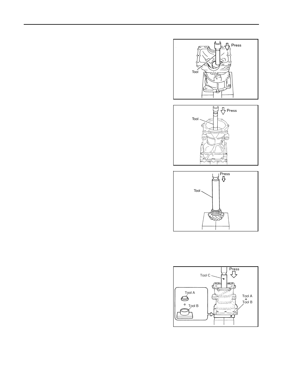
1.

Install a drive pinion adjusting shim of the same thickness as
was installed prior to disassembly. Press pinion rear bearing
outer race into gear carrier, using the drift [SST: ST1713000
(

).

CAUTION:

• At first, using a hammer, tap bearing outer race until it

becomes flush to gear carrier.

• Never reuse pinion rear bearing outer race.

2.

Press pinion front bearing outer race into gear carrier, using the
drift [SST: 33230000 (J-25805-01)].

CAUTION:

• At first, using a hammer, tap bearing outer race until it

becomes flush to gear carrier.

• Never reuse pinion front bearing outer race.

3.

Press pinion rear bearing inner race to drive pinion, using the
drift [SST: ST23860000 (

)].

CAUTION:

Never reuse pinion rear bearing inner race.

4.

After checking and adjusting the tooth contact and backlash of the drive gear and drive pinion following
the procedure below.

a.

Apply gear oil to the pinion rear bearing, and assemble the drive pinion to the gear carrier.

CAUTION:

Never assemble a collapsible spacer.

b.

Apply gear oil to pinion front bearing, and assemble pinion front
bearing inner race to drive pinion. Using the drifts and stand,
press pinion front bearing inner race to drive pinion as far as
drive pinion nut can be tightened.

CAUTION:

Never reuse pinion front bearing inner race.

c.

Temporarily tighten removed drive pinion nut to drive pinion.
NOTE:
Use removed drive pinion nut only for the preload measurement.

PDIA0056E

PDIA0067E

PDIA0068E

A

: Drift [SST: KV40100610 (J-26089)]

B

: Drift [SST: ST38220000 (

)]

C

: Drift [SST: ST23860000 (

)]

PDIA0057E

DRIVE PINION

DLN-119

< UNIT DISASSEMBLY AND ASSEMBLY >

[REAR FINAL DRIVE: R145]

C

E

F

G

H

I

J

K

L

M

A

B

DLN

N

O

P

d.

Fit the drive pinion socket (A) [SST: KV38108500 (

)]

onto the drive pinion spline. Using the pinion nut wrench (B)
[SST: KV38108400 (

)], tighten drive pinion nut to the

specified preload torque.

CAUTION:

Drive pinion nut is tightened with no collapsible spacer. Be
careful not to overtighten it. While measuring the preload,
tighten it by 5

°

 to 10

°

.

e.

Apply gear oil to side bearings, and install new side bearing
adjusting shims with the same thickness or re-install the old
ones to the same mounting position they were in prior to disas-
sembly. Set the drifts [SST: KV40100610 (J-26089)] to the right
and left. Install differential case assembly to gear carrier.

CAUTION:

• The drifts shall be placed on the center of the adjusting

shims.

• The pressure shall be as low as possible to install gear

carrier assembly to differential assembly. The maximum
pressure shall be 10 kN (1 ton, 1.1 US ton, 1.0 Imp ton).

• If adjusting shims are installed by tapping, gear carrier

may be damaged. Avoid tapping.

f.

Check and adjust the tooth contact. Refer to 

DLN-121, "Adjustment"

.

g.

Check and adjust the backlash. Refer to 

DLN-121, "Adjustment"

.

h.

Remove dummy cover set, and remove differential case assembly.

i.

Remove drive pinion nut and press drive pinion assembly out of
gear carrier.

CAUTION:

Never drop drive pinion assembly.

j.

Remove pinion front bearing inner race.

C

: Preload gauge [SST: ST3127S000 (J-25765-A)]

Standard

Pinion bearing preload

: Refer to 

DLN-126, "Pre-

load Torque"

.

JSDIA0266ZZ

PDIA0064E

PDIA0445E

DLN-120

< UNIT DISASSEMBLY AND ASSEMBLY >

[REAR FINAL DRIVE: R145]

DRIVE PINION

5.

Assemble collapsible spacer to drive pinion.

CAUTION:

• Be careful of the mounting direction of collapsible spacer.
• Never reuse collapsible spacer.

6.

Apply gear oil to pinion front bearing, and assemble pinion front
bearing inner race to drive pinion. Using the drifts and stand,
press pinion front bearing inner race to drive pinion as far as
drive pinion nut can be tightened.

CAUTION:

Never reuse pinion front bearing inner race.

7.

Apply anti-corrosive oil to the thread and seat of drive pinion nut,
and temporarily tighten drive pinion nut to drive pinion.

CAUTION:

Never reuse drive pinion nut.

8.

Fit the drive pinion socket (A) [SST: KV38108500 (

)]

onto the drive pinion spline. Using the pinion nut wrench (B)
[SST: KV38108400 (

)], adjust the drive pinion nut

tightening torque and pinion bearing preload torque.

CAUTION:

• Adjust the lower limit of the drive pinion nut tightening

torque first.

• If the preload torque exceeds the specified value, replace

collapsible spacer and tighten it again to adjust. Never
loosen drive pinion nut to adjust the preload torque.

• After adjustment, rotate drive pinion back and forth 2 to 3

times to check for unusual noise, rotation malfunction,
and other malfunctions.

9.

Install differential case assembly. Refer to 

DLN-111, "Assembly"

.

CAUTION:

Never install rear cover.

10. Install dummy cover set [SST: KV381086S1 (

)], and check drive gear runout, tooth contact,

and backlash. Refer to 

DLN-121, "Adjustment"

.

11. Remove dummy cover set [SST: KV381086S1 (

)], then install rear cover, and side oil seal.

Refer to 

DLN-111, "Assembly"

.

12. Check total preload torque. Refer to 

DLN-121, "Adjustment"

.

13. Install electric controlled coupling assembly. Refer to 

DLN-105, "Assembly"

.

SDIA2525E

A

: Drift [SST: KV40100610 (J-26089)]

B

: Drift [SST: ST38220000 (

)]

C

: Drift [SST: ST23860000 (

)]

C

: Preload gauge [SST: ST3127S000 (J-25765-A)]

Drive pinion tightening 
torque

: Refer to 

DLN-116, "Ex-

ploded View"

.

Standard

Pinion bearing preload

: Refer to 

DLN-126, "Pre-

load Torque"

.

PDIA0057E

JSDIA0266ZZ

DRIVE PINION

DLN-121

< UNIT DISASSEMBLY AND ASSEMBLY >

[REAR FINAL DRIVE: R145]

C

E

F

G

H

I

J

K

L

M

A

B

DLN

N

O

P

14. Check companion flange runout. Refer to 

DLN-107, "Adjustment"

.

Adjustment

INFOID:0000000005514272

TOTAL PRELOAD TORQUE

1.

Remove electric controlled coupling assembly. Refer to 

DLN-105, "Disassembly"

.

2.

Rotate drive pinion back and forth 2 to 3 times to check for unusual noise and rotation malfunction.

3.

Rotate drive pinion at least 20 times to check for smooth opera-
tion of the bearing.

4.

Fit drive pinion socket onto drive pinion spline. Measure the total
preload, using the preload gauge (A) [SST: 3127S000 (J-27565-
A)] and drive pinion socket (B) [SST: KV38108500 

)].

NOTE:
Total preload torque = Pinion bearing torque + Side bearing
torque

• If measured value is out of the specification, disassemble it to check and adjust each part. Adjust the pinion

bearing preload and side bearing preload.
Adjust the pinion bearing preload first, then adjust the side bearing preload.

DRIVE GEAR RUNOUT

1.

Remove rear cover. Refer to 

DLN-110, "Disassembly"

.

2.

Following the procedure below, install a dummy cover set [SST: KV381086S1 (

)] to gear car-

rier.

a.

Set dummy cover shims [SST: KV38108630 (

)] to the right and left side bearing adjusting

shims.

b.

Temporarily tighten dummy cover [SST: KV38108610 (

)] to gear carrier.

c.

Position dummy cover spacers [SST: KY38108621 (

)] to dummy cover [SST: 38108610

(

)].

d.

Tighten rear cover mounting bolts to the specified torque. Refer to 

DLN-116, "Exploded View"

.

e.

Tighten dummy cover spacer mounting bolts evenly to the specified torque.

Standard

Total preload torque

: Refer to 

DLN-126, "Pre-

load Torque"

.

When the preload torque is large

On pinion bearings:

Replace the collapsible spacer.

On side bearings:

Use thinner side bearing adjusting shims.

When the preload is small

On pinion bearings:

Tighten the drive pinion nut.

On side bearings:

Use thicker side bearing adjusting shims.

PDIA0048E

: 5.9 N·m (0.6 kg-m, 52 in-lb)


содержание   ..  494  495  496  497   ..