Nissan Murano Z51. Manual - part 495


  Главная      Nissan     Nissan Murano Z51 (2010 year) - Service Manual


поиск по сайту            


содержание   ..  493  494  495  496   ..


Nissan Murano Z51. Manual - part 495


DLN-114

< UNIT DISASSEMBLY AND ASSEMBLY >

[REAR FINAL DRIVE: R145]

DIFFERENTIAL ASSEMBLY

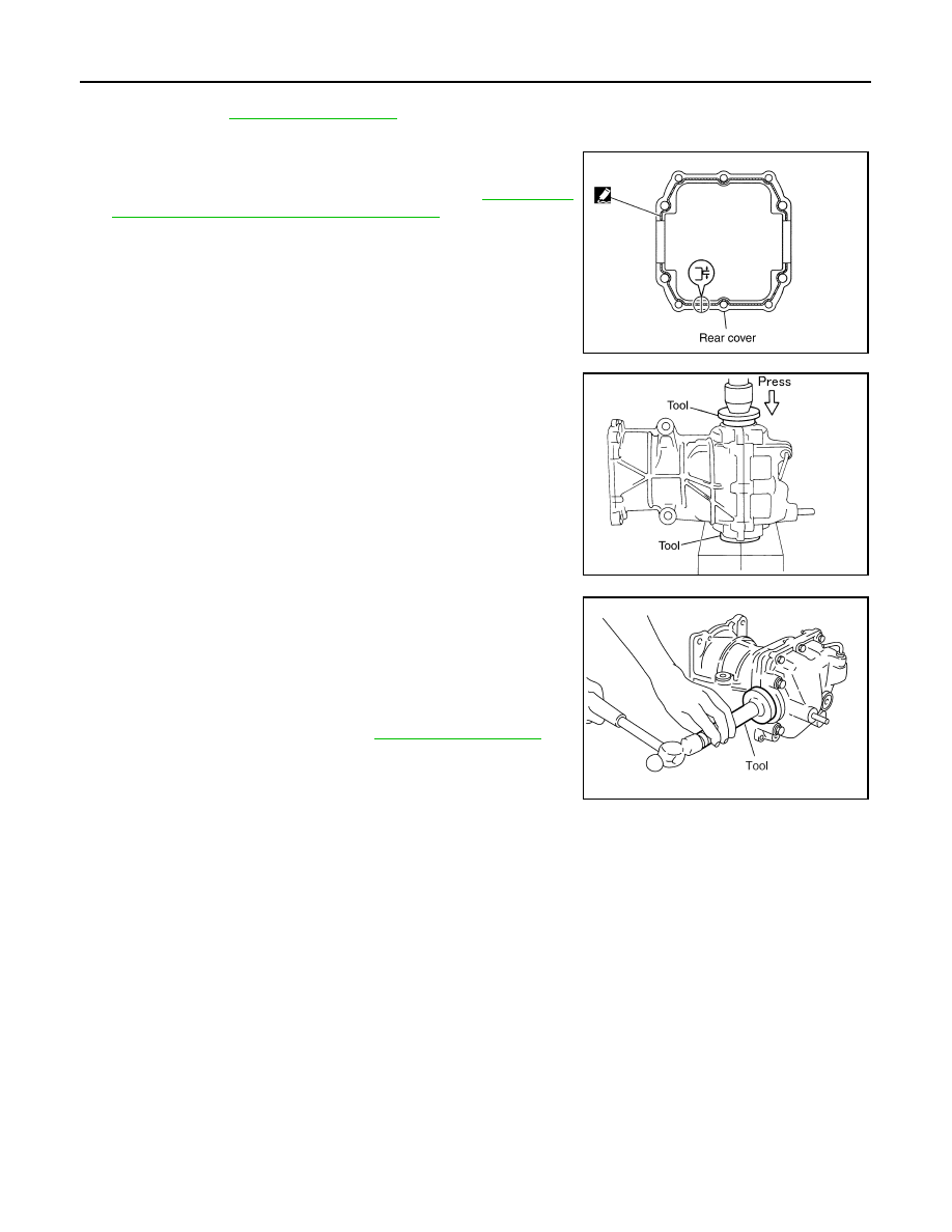
12. Install dummy cover set, check and adjust drive gear runout, tooth contact, backlash, and total preload

torque. Refer to 

DLN-121, "Adjustment"

.

13. Remove dummy cover set.

14. Apply liquid gasket to mating surface of rear cover. Overlap both

ends of the bead for at least 3 mm (0.12 in).
Use Genuine Silicone RTV or equivalent. Refer to 

GI-18, "Rec-

ommended Chemical Products and Sealants"

.

CAUTION:

Remove old gasket adhering to the mounting surfaces.
Also remove any moisture, oil, or foreign material adhering
to the mounting surfaces.

15. Set the drifts [SST: KV40100610 (J-26089)] to the right and left

side bearing adjusting shims individually. Compress differential
case assembly and side bearing to install rear cover.

CAUTION:

• The drift shall be placed on the center of the adjusting

shims.

• The pressure shall be as low as possible to install the rear

cover. The maximum pressure shall be 10 kN (1 ton, 1.0
Imp ton).

• If rear cover is forced in by tapping, rear cover may be

damaged by adjusting shims. Avoid tapping.

16. Tighten rear cover mounting bolts to the specified torque.

17. Using the drift [SST: KV38100200 (J-26233)], drive side oil seals

until it becomes flush with the carrier end.

CAUTION:

• Never reuse oil seals.
• When installing, do not incline oil seals.
• Apply multi-purpose grease onto oil seal lips, and gear oil

onto the circumference of oil seal.

18. Check total preload torque. Refer to 

DLN-121, "Adjustment"

.

Inspection After Disassembly

INFOID:0000000005514268

DRIVE GEAR AND DRIVE PINION

• Clean up the disassembled parts.
• If the gear teeth never mesh or line-up correctly, determine the cause and adjust or replace as necessary.
• If the gears are worn, cracked, damaged, pitted or chipped (by friction) noticeably, replace with new drive

gear and drive pinion as a set.

BEARING

• Clean up the disassembled parts.
• If any chipped (by friction), pitted, worn, rusted or scratched marks, or unusual noise from the bearing is

observed, replace as a bearing assembly (as a new set).

SIDE GEAR AND PINION MATE GEAR

• Clean up the disassembled parts.
• If any cracks or damage on the surface of the tooth is found, replace.
• If any worn or chipped mark on the contact sides of the thrust washer is found, replace.

SIDE GEAR THRUST WASHER AND PINION MATE THRUST WASHER

• Clean up the disassembled parts.
• If it is chipped (by friction), damaged, or unusually worn, replace.

PDIA0447E

PDIA0065E

PDIA0448E

DIFFERENTIAL ASSEMBLY

DLN-115

< UNIT DISASSEMBLY AND ASSEMBLY >

[REAR FINAL DRIVE: R145]

C

E

F

G

H

I

J

K

L

M

A

B

DLN

N

O

P

OIL SEAL

• Whenever disassembled, replace.
• If wear, deterioration of adherence (sealing force lips), or damage is detected on the lips, replace them.

DIFFERENTIAL CASE

• Clean up the disassembled parts.
• If any wear or crack on the contact sides of the differential case is found, replace.

COMPANION FLANGE

• Clean up the disassembled parts.
• If any chipped mark [about 0.1 mm, (0.004 in)] or other damage on the contact sides of the lips of the com-

panion flange is found, replace.

DLN-116

< UNIT DISASSEMBLY AND ASSEMBLY >

[REAR FINAL DRIVE: R145]

DRIVE PINION

DRIVE PINION

Exploded View

INFOID:0000000005514269

1.

Filler plug

2.

Gasket

3.

Drain plug

4.

Rear cover

5.

Side oil seal

6.

Side bearing adjusting shim

7.

Side bearing

8.

Drive gear

9.

Differential case

10. Pinion mate thrust washer

11.

Pinion mate gear

12. Pinion mate shaft

13. Lock pin

14. Side gear thrust washer

15. Side gear

16. Drive pinion

17. Pinion rear bearing

18. Drive pinion adjusting shim

19. Collapsible spacer

20. Gear carrier

21. Pinion front bearing

22. Drive pinion nut

23. Center oil seal

24. AWD solenoid harness

25. Electric controlled coupling

26. Coupling cover

27. Reamer bolt

28. Connector bracket

29. Front oil seal

30. Companion flange

31. Companion flange lock nut

A.

Oil seal lip

B.

Screw hole

: Apply gear oil.

: Apply anti-corrosive oil.

: Apply Genuine Silicone RTV or equivalent. Refer to 

GI-18, "Recommended Chemical Products and Sealants"

.

: Apply Genuine Medium Strength Thread Locking Sealant or equivalent. Refer to 

GI-18, "Recommended Chemical Prod-

ucts and Sealants"

.

Refer to 

GI-4, "Components"

 for symbols not described above.

JSDIA1027GB

DRIVE PINION

DLN-117

< UNIT DISASSEMBLY AND ASSEMBLY >

[REAR FINAL DRIVE: R145]

C

E

F

G

H

I

J

K

L

M

A

B

DLN

N

O

P

Disassembly

INFOID:0000000005514270

1.

Remove electric controlled coupling assembly. Refer to 

DLN-105, "Disassembly"

.

2.

Remove differential case assembly. Refer to 

DLN-110, "Disassembly"

.

3.

Fit drive pinion socket (A) [SST: KV38108500 (

)] onto

drive pinion spline. Remove drive pinion nut, using the pinion nut
wrench (B) [SST: KV38108400 (

)].

4.

Press drive pinion assembly out of gear carrier.

CAUTION:

Never drop drive pinion assembly.

5.

Remove pinion front bearing inner race.

6.

Remove collapsible spacer.

7.

Remove pinion rear bearing inner race from drive pinion, using
puller and bearing puller.

8.

Using a brass rod, tap pinion front bearing outer race evenly
from the 2 cutouts on gear carrier and remove pinion front bear-
ing outer race.

CAUTION:

Be careful not to damage gear carrier.

9.

Using a brass rod, tap drive pinion adjusting shim evenly from
the 2 cutouts on gear carrier and remove drive pinion adjusting
shim and pinion rear bearing outer race.

CAUTION:

Be careful not to damage the gear carrier.

JSDIA0265ZZ

PDIA0445E

PDIA0179E

SDIA0564E


содержание   ..  493  494  495  496   ..