Nissan Murano Z51. Manual - part 493


  Главная      Nissan     Nissan Murano Z51 (2010 year) - Service Manual


поиск по сайту            


содержание   ..  491  492  493  494   ..


Nissan Murano Z51. Manual - part 493


DLN-106

< UNIT DISASSEMBLY AND ASSEMBLY >

[REAR FINAL DRIVE: R145]

ELECTRIC CONTROLLED COUPLING

3.

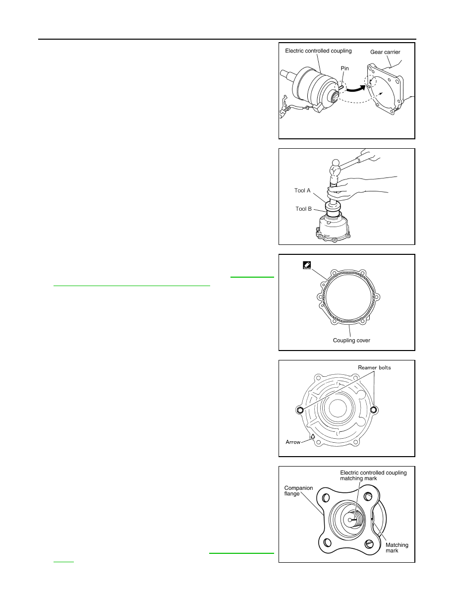
Install electric controlled coupling to spline of drive pinion inside
gear carrier.

CAUTION:

• Align the pin on electric controlled coupling with the

groove of gear carrier.

• Be careful not to damage center oil seal.

4.

Set AWD solenoid harness guide to gear carrier.

5.

Using the drifts, drive front oil seal until it becomes flush with the
coupling cover end.

CAUTION:

• Never reuse oil seal.
• When installing, never incline oil seal.
• Apply multi-purpose grease onto oil seal lips, and gear oil

onto the circumference of oil seal.

6.

Apply liquid gasket to mating surface of coupling cover. Overlap
both ends of the bead for at least 3 mm (0.12 in).
Use Genuine Silicone RTV or equivalent. Refer to 

GI-18, "Rec-

ommended Chemical Products and Sealants"

.

CAUTION:

Remove old gasket adhering to the mounting surfaces.
Also remove any moisture, oil, or foreign material adhering
to the mounting surfaces.

7.

Install coupling cover to gear carrier with arrow facing upward,
temporarily tighten reamer bolts to the positions shown in the
figure.

8.

Tighten reamer bolts and coupling cover mounting bolts to the
specified torque.

9.

Install connector bracket, and tighten bolts to the specified
torque.

10. Install companion flange.

NOTE:
When reusing electric controlled coupling, align the matching
mark of electric controlled coupling with the matching mark of
companion flange, then install companion flange.

11. Install companion flange lock nut with flange wrench (commer-

cial service tool), tighten to the specified torque.

CAUTION:

Never reuse companion flange lock nut.

12. Check companion flange runout. Refer to 

DLN-107, "Adjust-

ment"

.

PDIA0463E

A

: Drift [SST: KV38100200 (J-26233)]

B

: Drift [SST: ST27861000 (

)]

PDIA0449E

PDIA0613E

SDIA0587E

PDIA0455E

ELECTRIC CONTROLLED COUPLING

DLN-107

< UNIT DISASSEMBLY AND ASSEMBLY >

[REAR FINAL DRIVE: R145]

C

E

F

G

H

I

J

K

L

M

A

B

DLN

N

O

P

Adjustment

INFOID:0000000005514263

COMPANION FLANGE RUNOUT

1.

Fit a dial indicator onto the companion flange face (inner side of
the rear propeller shaft mounting bolt holes).

2.

Rotate companion flange to check for runout.

3.

Fit a test indicator to the inner side of companion flange (socket
diameter).

4.

Rotate companion flange to check for runout.

5.

If the runout value is outside the runout limit, follow the procedure below to adjust.

a.

Check for runout while changing the phase between companion flange and drive pinion by 90

°

 step, and

search for the position where the runout is the minimum.

b.

If the runout value is still outside of the limit after the phase has been changed, replace companion flange.

c.

If the runout value is still outside of the limit after companion flange has been replaced, possible cause will
be an assembly malfunction of drive pinion and electric controlled coupling, malfunctioning coupling bear-
ing, or malfunctioning of electric controlled coupling.

Inspection After Disassembly

INFOID:0000000005514264

DRIVE GEAR AND DRIVE PINION

• Clean up the disassembled parts.
• If the gear teeth never mesh or line-up correctly, determine the cause and adjust or replace as necessary.
• If the gears are worn, cracked, damaged, pitted or chipped (by friction) noticeably, replace with new drive

gear and drive pinion as a set.

BEARING

• Clean up the disassembled parts.
• If any chipped (by friction), pitted, worn, rusted or scratched marks, or unusual noise from the bearing is

observed, replace as a bearing assembly (as a new set).

SIDE GEAR AND PINION MATE GEAR

• Clean up the disassembled parts.
• If any cracks or damage on the surface of the tooth is found, replace.
• If any worn or chipped mark on the contact sides of the thrust washer is found, replace.

SIDE GEAR THRUST WASHER AND PINION MATE THRUST WASHER

• Clean up the disassembled parts.
• If it is chipped (by friction), damaged, or unusually worn, replace.

OIL SEAL

• Whenever disassembled, replace.
• If wear, deterioration of adherence (sealing force lips), or damage is detected on the lips, replace them.

DIFFERENTIAL CASE

• Clean up the disassembled parts.
• If any wear or crack on the contact sides of the differential case is found, replace.

COMPANION FLANGE

• Clean up the disassembled parts.

Limit

Companion flange runout

: Refer to 

DLN-126, "Com-

panion Flange Runout"

.

Limit

Companion flange runout

: Refer to 

DLN-126, "Com-

panion Flange Runout"

.

PDIA0439E

DLN-108

< UNIT DISASSEMBLY AND ASSEMBLY >

[REAR FINAL DRIVE: R145]

ELECTRIC CONTROLLED COUPLING

• If any chipped mark [about 0.1 mm, (0.004 in)] or other damage on the contact sides of the lips of the com-

panion flange is found, replace.

DIFFERENTIAL ASSEMBLY

DLN-109

< UNIT DISASSEMBLY AND ASSEMBLY >

[REAR FINAL DRIVE: R145]

C

E

F

G

H

I

J

K

L

M

A

B

DLN

N

O

P

DIFFERENTIAL ASSEMBLY

Exploded View

INFOID:0000000005514265

1.

Filler plug

2.

Gasket

3.

Drain plug

4.

Rear cover

5.

Side oil seal

6.

Side bearing adjusting shim

7.

Side bearing

8.

Drive gear

9.

Differential case

10. Pinion mate thrust washer

11.

Pinion mate gear

12. Pinion mate shaft

13. Lock pin

14. Side gear thrust washer

15. Side gear

16. Drive pinion

17. Pinion rear bearing

18. Drive pinion adjusting shim

19. Collapsible spacer

20. Gear carrier

21. Pinion front bearing

22. Drive pinion nut

23. Center oil seal

24. AWD solenoid harness

25. Electric controlled coupling

26. Coupling cover

27. Reamer bolt

28. Connector bracket

29. Front oil seal

30. Companion flange

31. Companion flange lock nut

A.

Oil seal lip

B.

Screw hole

: Apply gear oil.

: Apply anti-corrosive oil.

: Apply Genuine Silicone RTV or equivalent. Refer to 

GI-18, "Recommended Chemical Products and Sealants"

.

: Apply Genuine Medium Strength Thread Locking Sealant or equivalent. Refer to 

GI-18, "Recommended Chemical Prod-

ucts and Sealants"

.

Refer to 

GI-4, "Components"

 for symbols not described above.

JSDIA1027GB


содержание   ..  491  492  493  494   ..