Nissan Murano Z51. Manual - part 460


  Главная      Nissan     Nissan Murano Z51 (2010 year) - Service Manual


поиск по сайту            


содержание   ..  458  459  460  461   ..


Nissan Murano Z51. Manual - part 460


DLK-348

< REMOVAL AND INSTALLATION >

[WITH INTELLIGENT KEY SYSTEM]

REAR DOOR LOCK

REAR DOOR LOCK

DOOR LOCK

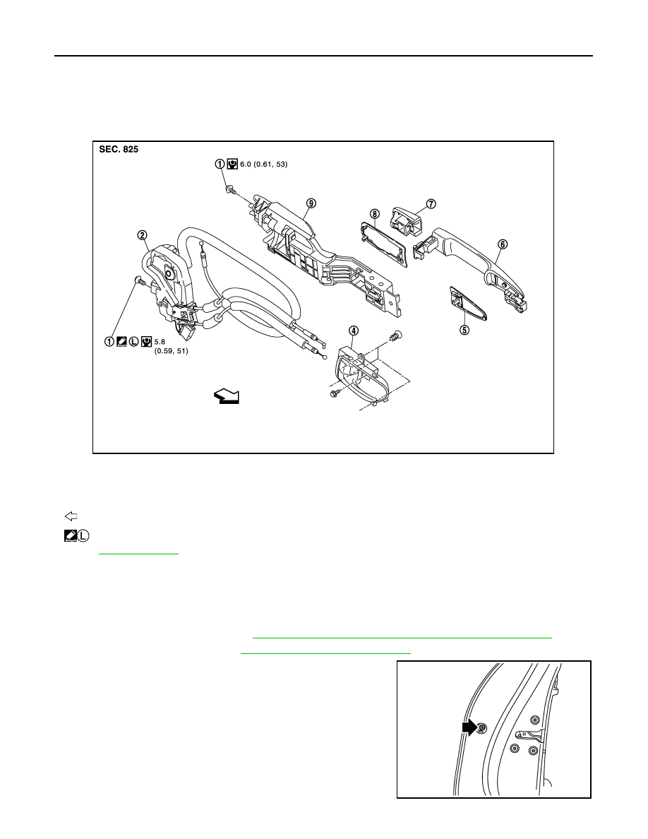
DOOR LOCK : Exploded View

INFOID:0000000005517817

DOOR LOCK : Removal and Installation

INFOID:0000000005517818

REMOVAL

1.

Fully close rear door glass.

2.

Remove rear door finisher. Refer to 

INT-16, "REAR DOOR FINISHER : Removal and Installation"

.

3.

Remove sealing screen. Refer to 

GW-25, "Removal and Installation"

.

4.

Remove door side grommet, and loosen TORX bolt from grom-
met hole.

1.

TORX bolt

2.

Door lock assembly

3.

Inside handle cap

4.

Inside handle

5.

Front gasket

6.

Outside handle

7.

Outside handle escutcheon

8.

Rear gasket

9.

Outside handle bracket

: Vehicle front

  : Apply genuine high strength thread locking sealant or equivalent.

Refer to 

GI-4, "Components"

 for symbols in the figure.

JMKIA1803GB

JMKIA1467ZZ

REAR DOOR LOCK

DLK-349

< REMOVAL AND INSTALLATION >

[WITH INTELLIGENT KEY SYSTEM]

C

D

E

F

G

H

I

J

L

M

A

B

DLK

N

O

P

5.

While pulling outside handle, remove outside handle escutch-
eon.

6.

While pulling outside handle (1), slide toward rear of vehicle to
remove outside handle.

7.

Remove front gasket and rear gasket.

8.

While pulling outside handle bracket, slide toward rear of vehicle
to remove outside handle bracket.

9.

Reach in to separate outside handle cable connection on outside handle bracket.

10. Disconnect harness connector from door lock actuator.

11. Remove door lock mounting bolts.

12. Remove door lock assembly.

INSTALLATION

Install in the reverse order of removal.

CAUTION:

Check door open/close, lock/unlock operation after installation. 

INSIDE HANDLE

JMKIA0560ZZ

JMKIA0524ZZ

PIIB5814E

DLK-350

< REMOVAL AND INSTALLATION >

[WITH INTELLIGENT KEY SYSTEM]

REAR DOOR LOCK

INSIDE HANDLE : Exploded View

INFOID:0000000005517819

INSIDE HANDLE : Removal and Installation

INFOID:0000000005517820

REMOVAL

1.

Remove rear door finisher. Refer to 

INT-16, "REAR DOOR FINISHER : Removal and Installation"

.

2.

Remove inside handle mounting screws.

3.

Disconnect inside handle cable, and then remove inside handle.

INSTALLATION

Install in the reverse order of removal.

CAUTION:

Check door open/close, lock/unlock operation after installation. 

OUTSIDE HANDLE

1.

TORX bolt

2.

Door lock assembly

3.

Inside handle cap

4.

Inside handle

5.

Front gasket

6.

Outside handle

7.

Outside handle escutcheon

8.

Rear gasket

9.

Outside handle bracket

: Vehicle front

  : Apply genuine high strength thread locking sealant or equivalent.

Refer to 

GI-4, "Components"

 for symbols in the figure.

JMKIA1803GB

REAR DOOR LOCK

DLK-351

< REMOVAL AND INSTALLATION >

[WITH INTELLIGENT KEY SYSTEM]

C

D

E

F

G

H

I

J

L

M

A

B

DLK

N

O

P

OUTSIDE HANDLE : Exploded View

INFOID:0000000005517821

OUTSIDE HANDLE : Removal and Installation

INFOID:0000000005517822

REMOVAL

1.

Remove rear door finisher. Refer to 

INT-16, "REAR DOOR FINISHER : Removal and Installation"

.

2.

Fully close rear door glass.

3.

Remove sealing screen. Refer to 

GW-25, "Removal and Installation"

.

4.

Remove door side grommet, and loosen TORX bolt from grom-
met hole.

1.

TORX bolt

2.

Door lock assembly

3.

Inside handle cap

4.

Inside handle

5.

Front gasket

6.

Outside handle

7.

Outside handle escutcheon

8.

Rear gasket

9.

Outside handle bracket

: Vehicle front

  : Apply genuine high strength thread locking sealant or equivalent.

Refer to 

GI-4, "Components"

 for symbols in the figure.

JMKIA1803GB

JMKIA1467ZZ


содержание   ..  458  459  460  461   ..