содержание .. 455 456 457 458 ..
Nissan Murano Z51. Manual - part 457
DLK-336
< REMOVAL AND INSTALLATION >
[WITH INTELLIGENT KEY SYSTEM]
BACK DOOR
BACK DOOR HINGE : Removal and Installation
INFOID:0000000005517802
REMOVAL
1.
Remove back door assembly. Refer to
DLK-331, "BACK DOOR ASSEMBLY : Removal and Installation"
2.
Remove luggage side finisher lower and luggage side finisher upper. Refer to
.
3.
Using a remover tool, remove headlining clip at the rear side of headlining. Refer to
(NORMAL ROOF),
INT-30, "SUNROOF : Exploded View"
(SUNROOF).
4.
Remove rear side of headlining.
5.
Remove power back door drive assembly. Refer to
DLK-354, "POWER BACK DOOR DRIVE ASSEMBLY
.
6.
Remove back door hinge mounting nuts (body side), and then remove back door hinge.
INSTALLATION
Install in the reverse order of removal.
CAUTION:
• Check back door open/close operation after installation.
• Check back door hinge rotating part for poor lubrication. If necessary, apply body grease.
• When removing and installing back door assembly, perform the fitting adjustment. Refer to
"BACK DOOR ASSEMBLY : Adjustment"
.
• After installation, apply touch-up paint (the body color) onto the head of back door hinge mounting
nuts.
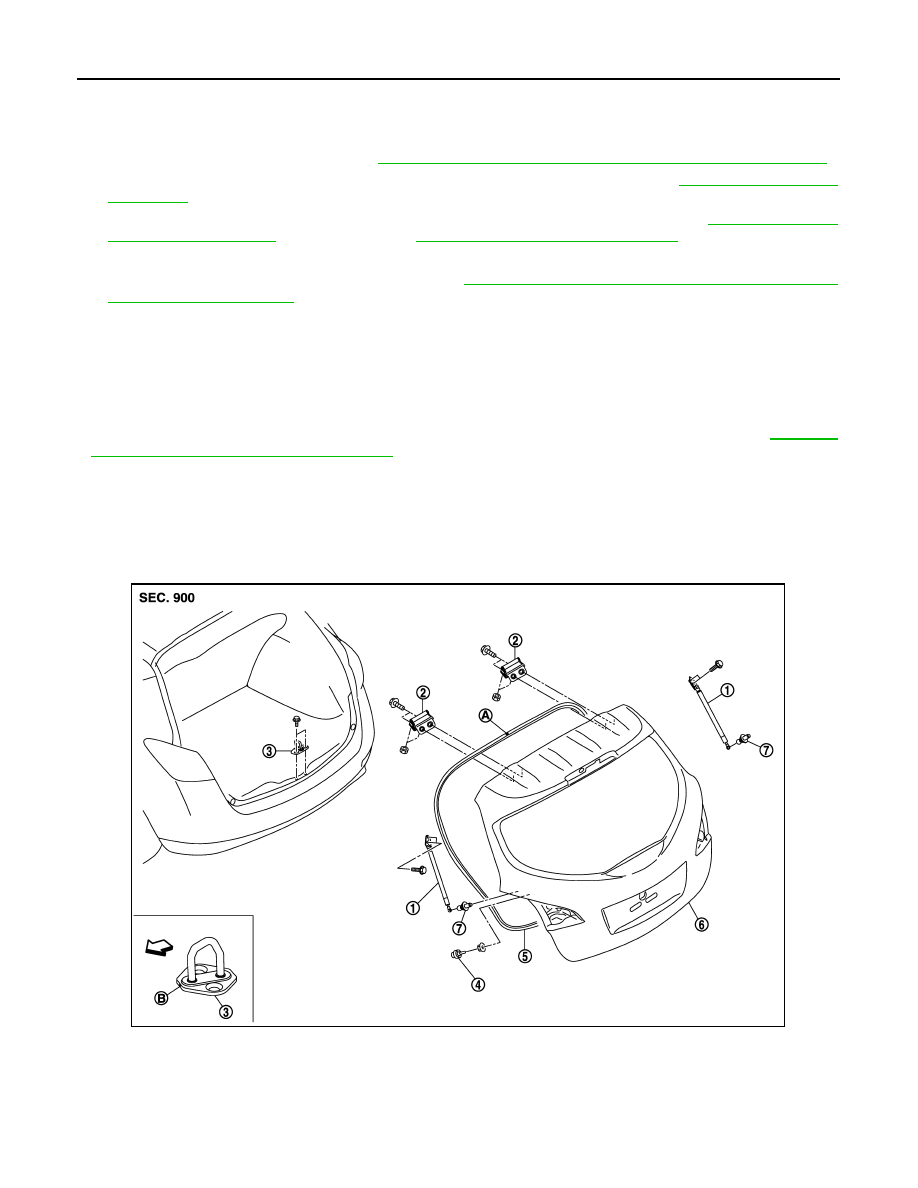
BACK DOOR STAY
BACK DOOR STAY : Exploded View
INFOID:0000000005517803
1.
Back door stay
2.
Back door hinge
3.
Back door striker
4.
Bumper rubber
5.
Back door weather-strip
6.
Back door assembly
7.
Stud ball
A
: Center mark
B
: Front mark
JMKIA3496ZZ